Spring-Applied Holding Brakes in Custom Humanoid Actuators: Power-Off Posture Retention, Overexcitation Thermal Budgets, and RFQ Acceptance Protocols
Specify spring-applied holding brakes for your custom humanoid actuator: compare power-off retention, thermal budgets, and FAT evidence before sending an RFQ.
Integrated spring-applied holding brakes vs. unbraked humanoid joints: Shortlist a power-off brake when gravity sag or prolonged motor-current holding is unacceptable. An unbraked, backdrivable joint needs motor torque or an independent mechanical support to retain posture. A brake can hold a shaft without coil power, but it cannot by itself keep a walking robot balanced or retain a load after a downstream transmission failure.
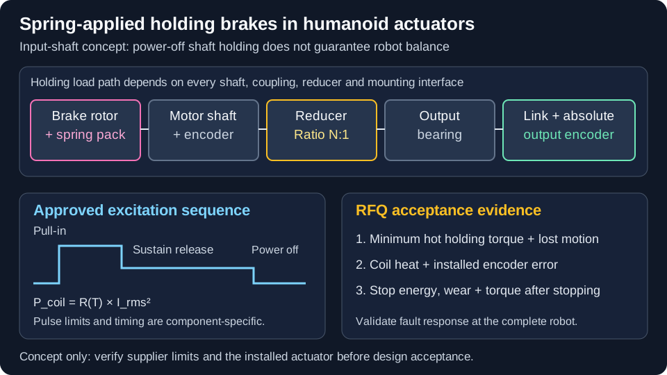
Published and reviewed: 1 November 2026. This global, English-language sourcing guide serves mechatronics leads, hardware architects, and OEM/ODM procurement teams specifying custom humanoid actuators. Scope: integrated rotary joints with frameless motors, reducers, encoders, and electromechanical holding brakes. The calculations and FAT proposals are reproducible design examples, not measured actuator results, supplier guarantees, or certification evidence. Commercial, household, medical, and industrial deployments require their own application and jurisdiction assessment.
Executive Sourcing & Architecture Summary
- Define the safe state: Braking the joints does not guarantee bipedal stability. Distinguish supported parking, stationary task holding, and fault stopping; validate the complete robot response.
- Compare input and output placement: Input-side brakes benefit from gear ratio but depend on the reducer and couplings. Output-side brakes can bypass some transmission failure paths at a higher torque requirement.
- Specify the release profile: Use only supplier-approved pull-in and reduced holding excitation. Calculate coil heat from RMS current and resistance, including PWM ripple and repeated pull-in pulses.
- Validate hot holding torque: Spring force does not make friction torque temperature-independent. Check torque, release margin, and encoder error at the installed thermal limits.
- Buy evidence: Request minimum guaranteed holding torque, switching-time conditions, single-stop energy, lifetime friction work, and post-stop holding tests for the exact brake variant.
For a brake integration review, send your parking load, torque-speed envelope, release duty, mass target, and CAD envelope through the engineering inquiry desk. The custom humanoid actuator modules page outlines the configuration scope.
1. The Kinematic Dilemma: Why Industrial Brake Logic Fails in Humanoids
In a fixed-base arm, a holding brake can prevent gravity-driven joint movement after a validated stopping sequence. Engagement has a finite electrical and mechanical delay: power removal does not instantly freeze an arm or establish a safe state. IEC 60204-1 addresses machine electrical equipment and stopping functions; the stop design depends on the machine risk assessment.
A dynamically balancing humanoid may lose balance even if all shafts are held. Whether it falls depends on posture, support contacts, momentum, payload, and available fault-response energy. Treat the following as distinct engineering use cases, not standardized safe-state categories:
- Supported parking, transport, or docking: Engage the brakes after the robot is seated or mechanically supported. Verify joint deflection and the complete holding load path, including shafts, couplings, reducer, and fixtures.
- Stationary task holding: Transfer the load from motor torque to the brake only after verifying engagement and load retention. Motor current may then be reduced if the robot-level stability and restart strategy permit it.
- Fault stopping during motion: A controlled deceleration or descent requires sufficient control authority and stored energy. Total bus loss may remove that option; define and test the fallback rather than assuming a crouch remains possible. Specify engagement speed at the brake shaft, not merely at the joint output.
Standards boundary, checked 1 November 2026: ISO/CD 25785-1 is a committee draft under development for dynamically stable industrial mobile robots, not a published compliance basis. ISO 13849-1:2023 supplies a safety-control design methodology; it does not prescribe the safety functions or required performance level for this application. A dual-channel brake driver alone establishes neither a Performance Level nor validated Safe Brake Control (SBC).
2. Holding Brake Mechanisms: Spring-Applied vs. Permanent Magnet vs. Dog Clutches
Actuator architects have three primary mechanical principles for power-off holding in robotic joints: spring-applied electromagnetic brakes, permanent-magnet (PM) electromagnetic brakes, and bi-stable electromechanical dog clutches.
2.1 Electromagnetic Spring-Applied Friction Brakes
Springs press an armature and friction rotor together when the coil is de-energized. Energizing the coil pulls the armature against the spring force and releases the shaft.
- Advantages: Power-off shaft holding and, for appropriately rated variants, emergency friction braking.
- Limitations: Electrical power is needed during release; temperature, contamination, wear, and mounting conditions affect performance. Dynamic braking permission must be stated by the supplier.
2.2 Permanent-Magnet (PM) Holding Brakes
A permanent magnetic field supplies the clamping force; a correctly polarized coil field releases the brake. Magnetic circuit, magnet grade, and friction pairing determine its operating limits.
- Advantages: Compact holding arrangements and potentially low lost motion, depending on construction.
- Limitations: Confirm hot torque, polarity, release-voltage window, and emergency-stop capability for the exact model. A magnet's flux temperature coefficient is not a universal brake-torque derating coefficient.
2.3 Bi-Stable Electromechanical Dog Clutches (Tooth Clutches)
Intermeshing teeth provide positive holding after alignment. A bistable mechanism retains its last state without continuous power; it does not necessarily engage when power fails.
- Advantages: Low continuous holding power and a positive mechanical load path once fully engaged.
- Limitations: Require an allowed relative speed, angular alignment, and engagement confirmation. Do not assume a tooth lock can absorb emergency friction work.
Use this decision matrix to define comparable supplier submissions:
| Technical & Sourcing Parameter | Spring-Applied Friction Brake | Permanent-Magnet Friction Brake | Bi-Stable Tooth Clutch | Evidence to Request in RFQ |
|---|---|---|---|---|
| Power-loss state | Springs apply after flux decays | Magnetic field applies, subject to design | Usually retains last state | State diagram and fault test |
| Torque and package | Model-dependent friction radius and spring force | Model-dependent magnetic circuit and friction pair | Tooth strength and engagement govern | Minimum torque, CAD, bore, mass, tolerances |
| Holding lost motion | Hub and rotor connection contribute | Depends on armature and hub construction | Tooth pitch and clearance contribute | Measured lost motion and torsional stiffness |
| Temperature response | Friction torque and coil release margin need validation | Magnet, coil, and friction limits need validation | Fits, actuator, and material limits still apply | Hot/cold torque and release curves |
| Dynamic stop capability | Only within approved speed and energy limits | Only if explicitly rated | No friction-stop assumption | Single-stop energy and lifetime work limits |
| Electrical consumption | Coil energized to release; reduction may be supported | Cancellation current needed to release | Switching pulses; controller may still draw power | Coil resistance, current profile, bus consumption |
| Hollow-shaft integration | Available on selected designs | Confirm exact model geometry | Confirm actuator and indexing package | Usable bore, cable path, sealing arrangement |
| Commercial comparison | Quote exact configuration | Quote exact configuration | Quote exact configuration | Same quantities, tooling, lead time, test scope |
Catalog evidence, not a generic joint rating: The Mayr ROBA-servostop catalog, p. 8 specifies temperature derating for its Cobot series. The Kendrion Servo Slim Line catalog, p. 8 separately lists minimum static torque, nominal torque, stop energy, and switching conditions; its nominal backlash is 1°. Neither catalog supports treating all compact brakes as zero-backlash devices.
3. Kinematic Placement: Motor Input Shaft vs. Reducer Output Flange
A critical mechatronic architectural decision is whether to place the holding brake on the high-speed rotor input shaft (before the reducer) or directly on the low-speed joint output flange (after the reducer).
Configuration A: input-shaft brake
[Brake / motor rotor] -> [Reducer N:1] -> [Output bearing] -> [Limb]
Ideal static screening: T_brake = T_joint / N
Example: 120 Nm / 80 = 1.5 Nm, before margins and derating

Configuration B: output-flange brake
[Motor] -> [Reducer N:1] -> [Brake / output bearing] -> [Limb]
Ideal static screening: T_brake = T_joint
Example: 120 Nm, before margins and derating
For a preliminary input-side screen, define T_brake,min >= S_F × T_joint / (N × k_transfer). Here S_F is the chosen load margin and k_transfer is a supplier-agreed conservative transfer factor, not running gearbox efficiency. Static holding and backdriving cannot be approved from forward running efficiency alone.
Worked assumption: At T_joint = 120 Nm, N = 80, S_F = 2.0, and k_transfer = 0.80, the minimum brake-side requirement is 3.75 Nm. Apply the supplier's temperature and wear derating when selecting a nominal rating. This example is not a product recommendation or a universal safety factor.
- Input-side trade-off: Lower brake torque demand, but a failed reducer or coupling can interrupt holding. Gear lost motion and torsional wind-up remain downstream; measure link deflection under changing payload.
- Output-side trade-off: Higher direct torque demand and different packaging, but potentially a shorter independent holding path. Compare actual CAD, mass, and failure containment rather than assigning a generic size or mass penalty.
Use the load case and mounting plane when requesting custom humanoid actuator module feasibility feedback; include the supported parking posture and the hot holding requirement.
4. Integrated Actuator Architecture & Brake Subassembly
The diagram shows one possible coaxial integration and the distinction between release excitation and power-off holding. It is a concept diagram, not a dimensioned manufacturing drawing or a tested safety architecture.
Key subassembly interfaces:
- Coil housing: Fix it to the stationary chassis and define a heat path that does not depend solely on adjacent encoder mounts.
- Spring pack: Confirm clamping force, fatigue assumptions, and the supplier's permissible switching cycle count.
- Armature: Control travel, guidance, and runout using the selected brake drawing, including thermal expansion and wear.
- Friction rotor and hub: Verify torque transfer, axial freedom where required, and the assembled lost-motion budget.
- Air gap: Specify the supplier's nominal and end-of-life limits. Too much gap can prevent release; too little clearance or excess runout can cause drag.
5. Electrical & Thermal Management: Overexcitation and PWM Chopping
Releasing the brake requires enough magnetic force to overcome the spring pack at the largest allowed air gap. Once the armature is attracted, a lower current may sustain release. The necessary pull-in and holding currents depend on the magnetic circuit, temperature, air gap, and coil design.
5.1 Reproducible Coil-Power Budget
For a hypothetical 32 ohm winding at a fixed temperature:
24 V DC: I = 24 / 32 = 0.75 A; P = 24² / 32 = 18 W
 8 V DC: I =  8 / 32 = 0.25 A; P =  8² / 32 =  2 W
22 identical coils: 396 W versus 44 W of winding loss
The ideal reduction is 88.9%. These are arithmetic results, not measured savings or a claim that any 24 V brake will release at 8 V. Battery input also includes driver losses; runtime depends on all robot loads. Temperature rise requires the installed thermal resistance, ambient temperature, and motor/reducer heat load.
5.2 Supplier-Approved Overexcitation and PWM Reduction
Overexcitation means temporarily exceeding the coil's designated continuous excitation, within the manufacturer's pulse limits. A normal 24 V release coil is not automatically suitable for a 24-to-8 V profile. Mayr's Cobot catalog explicitly lists 24 V pull-in and 8 V holding for that series (p. 8); Kendrion specifies different profiles for selected variants. Confirm the part number, approved duration, and minimum hot release margin.
Pull-in: apply approved U_O for approved t_over; confirm release
Sustain release: regulate current above the hot minimum holding current
Apply brake: remove excitation; discharge inductive energy within ratings
Verify: torque build-up, load transfer, and safe restart before motor motion
For PWM operation, calculate winding loss as P_coil = R(T) × I_rms². A 33% voltage duty ratio only approximates the 8 V DC example when the driver topology and coil inductance maintain sufficiently smooth current. With large ripple, I_rms exceeds mean current; duty ratio alone cannot establish copper loss. Log the current waveform, switching frequency, suppression circuit, and hot resistance.
Include repeated pull-in heating: P_avg = (P_pull × t_pull + P_hold × t_hold) / t_cycle, using measured phase powers and the actual cycle. Specify pulse timeout and recovery behavior so a stuck pull-in command cannot exceed the coil's thermal rating. Reduced excitation is an energy feature; SBC still needs a separately validated safety architecture.
6. Dynamic Impact Tolerance, Backlash Budgeting, and Friction Glazing
Walking, payload handoffs, transport vibration, and external contact create different torque and shock cases. Measure or model these cases at the installed brake shaft; housing acceleration alone cannot establish the required holding torque.
6.1 Dynamic Slipping vs. Static Holding Safety Factor
A simplified uniform-pressure friction model is:
T_slip = F_spring × mu_s × r_mean × z
r_mean = (2/3) × (r_outer³ - r_inner³) / (r_outer² - r_inner²)
F_spring is axial clamp force, mu_s is the tested static friction coefficient, and z counts active friction faces. Dynamic friction, wear state, and actual pressure distribution can change the result. Use the supplier's minimum guaranteed torque and installed tests for selection rather than assumed friction coefficients.
Select the holding margin from gravity, payload uncertainty, disturbances, allowable slip, and the consequence of failure. The S_F = 2.0 in Section 3 is an example, not a universal requirement and not proof against every shock load. Check both minimum torque for retention and maximum torque for gearbox/structure loading.
6.2 Emergency Stop Energy and Friction Wear
A starting estimate for rotating kinetic energy is E_k = 0.5 × J_total × omega², where J_total includes rotor, brake hub, and link inertia reflected by J_link / N² at the motor shaft. As an illustrative case, J_total = 0.0002 kg·m² at 4,500 rpm gives about 22.2 J before any gravity or external work.
The brake may also absorb work from a descending payload or external load. Account for that work and any energy actually removed by the drive; do not assume regeneration remains available after bus loss. Compare residual brake energy with the allowed single-stop energy, engagement speed, cumulative friction work, cooling interval, and remaining holding torque.
Repeated dynamic stops can wear or glaze a friction lining. There is no generic lifetime allowance of 100–250 full-speed stops across all holding brakes. Freeze the supplier's specific energy/speed/cycle envelope and require post-stop torque checks. Routine motion should use controlled motor deceleration where the validated system permits it.
7. Thermal Isolation Architecture: Protecting High-Resolution Absolute Encoders
Brake coil heating can change the encoder mounting geometry and sensor temperature. Treat this as an integration risk to measure, not evidence that every compact joint will drift or fail.
- Optical encoders: Differential expansion among housing, shaft, bracket, and code disc can alter alignment. Evaluate the actual materials and datum stack; nominal bit resolution does not establish installed angular accuracy.
- Magnetic encoders: Verify permitted air gap, temperature compensation, shielding, and sensitivity to the brake's magnetic field and switching transients. The acceptable gap is specific to the encoder model.
Engineering Mitigations in Custom Actuator CAD
- Selective thermal isolation: Low-conductivity spacers may protect encoder mounts, but can also raise coil temperature or reduce mounting stiffness. Check both consequences.
- Dedicated chassis conduction: Provide an intentional heat path from coil housing to the external shell while controlling encoder datum expansion.
- Temperature and error mapping: Measure coil, housing, motor, and encoder temperatures during release and switching. Compare angular error against an independent reference at the hot condition; record sensor location and cooling boundary.
Use those records to set an operating limit and fault response; an embedded thermistor alone does not validate the coil's hottest spot or the encoder's error budget.
8. Quality Inspection & Factory Acceptance Test (FAT) Matrix
Hardware procurement teams should negotiate and freeze the following factory acceptance protocols before releasing prototype purchase orders. The acceptance criteria below are engineering proposals, to be finalized between OEM architects and the manufacturing team using joint load cases and supplier ratings.
| Inspection Protocol | Measured Technical Parameter | Acceptance Proposal | Test Setup & Instrumentation Record | Engineering Decision Gate |
|---|---|---|---|---|
| 1. Static holding torque | Minimum slip torque in both directions, cold and hot | Meet agreed design minimum after applicable derating; distinguish minimum from nominal torque | Fix brake housing, isolate motor torque, support the load, ramp calibrated shaft torque to slip; record temperature, conditioning, uncertainty | Retain worst-case load without exceeding allowed structural torque |
| 2. Engagement and release latency | Command-to-release and command-to-agreed holding-torque threshold | Meet the robot stopping budget across bus, temperature, and air-gap limits | Current probe, torque transducer, encoder, synchronized oscilloscope; state flyback circuit | Demonstrate timing margin; shaft motion alone does not prove full torque |
| 3. Released drag torque | Residual drag over speed and temperature | Within the agreed efficiency and heating allocation | Precision torque fixture under approved reduced excitation, hot/cold speed sweep | Prevent unwanted rubbing and thermal load |
| 4. Coil and encoder thermal behavior | Winding/housing temperatures and encoder error | Remain within component ratings and agreed joint accuracy budget | Installed housing, specified ambient/cooling, repeated pull-ins and worst duty; log temperatures to stabilization | Validate heat path and release margin |
| 5. Electrical insulation | Resistance and withstand with documented circuit isolation | Follow applicable insulation design and supplier-approved test voltage/duration | Calibrated tester; disconnect sensitive electronics as required; record leakage and setup | Establish insulation evidence; this alone does not establish CE, UL, or functional safety compliance |
| 6. Mounting runout and air gap | Hub/armature runout and working clearance | Meet controlled drawing limits at assembly and hot condition | Dial/CMM fixture with stated datums; correlate with assembled drag | Avoid chatter, uneven wear, and release failure |
| 7. Emergency braking endurance | Energy, speed, temperature, stop count, post-test torque | Stay inside supplier-approved envelope and retain the agreed minimum torque | Guarded fixture with representative inertia and load work; record cooling intervals and inspect after the sequence | Verify dynamic rating separately from static holding |
Record fixture revision, serial/lot identification, calibration status, sample count, measurement uncertainty, and pass/fail disposition. Apply destructive slip and endurance tests only to the agreed sample plan; do not consume the emergency-stop life of every shipped unit without accounting for it.
9. 10-Point Engineering & Procurement Checklist for Humanoid Actuator Brake RFQs
Before submitting an engineering RFQ for custom humanoid actuator modules with integrated holding brakes, ensure all specifications are formally documented:
- 1. Kinematic Mounting Plane: Confirm whether the brake sits on the motor rotor input shaft or the joint output flange; specify gearbox ratio
N, static transfer assumptions, and the complete holding load path. - 2. Static Breakaway Torque: Specify minimum break-away slip torque in both clockwise and counter-clockwise directions at the specified cold and hot operating limits; record winding and friction-interface conditions.
- 3. Air Gap (
s_a) Limits & Field Wear Budget: Use the selected drawing to define manufacturing clearance, tolerance stack, and the end-of-life limit after the agreed wear test. - 4. Dual-Voltage Electrical Sizing: Specify overexcitation pull-in voltage (
U_O), maximum pull-in pulse duration (t_over), and reduced holding voltage (U_H), minimum hot current, PWM frequency, RMS current, and allowable bus ripple. - 5. Dynamic Stop Energy Rating (
W_max): Quantify total reflected rotor and link inertia, maximum brake engagement speed, and required lifetime emergency stop cycle count, single-stop energy, and cooling interval. - 6. Axial Stack & Hollow-Shaft Envelope: Define strict axial length envelope limits (e.g.,
<= 14 mmallocated to brake), minimum hollow bore clear diameter, and wire harness chafe protection. - 7. Fast De-energization Clamping Circuit: State whether freewheeling flyback diodes, Zener snubbers, or varistors are integrated inside the actuator housing or located on the external servo drive PCBA.
- 8. Thermal Isolation & Encoder Proximity: Specify coil and encoder temperature limits plus installed angular-error limits during heating and switching.
- 9. Environmental Ingress & Contamination: Define IP sealing ratings (e.g., IP54 or IP65) and verify that friction surfaces are protected against motor grease migration from the strain-wave gearset.
- 10. Quality Deliverables & Traceability: Require serialized CMM runout records, coil resistance and inductance certificates, holding torque verification curves, and lot-tracked friction material batch data.
10. Frequently Asked Questions (FAQ)
Why not use a standard permanent-magnet brake instead of a spring-applied brake in humanoids?
Compare the exact variants rather than selecting by mechanism alone. Check hot minimum holding torque, release voltage and polarity, lost motion, package, and permitted emergency braking work. Spring-applied friction brakes also require temperature derating; neither mechanism automatically establishes robot-level safety.
How do spring-applied brakes impact joint zero-position homing after an emergency stop?
An absolute encoder can report its encoded position after restart, but retained multi-turn state, calibration, mechanical slip, and power-loss behavior still require verification. BiSS-C and SSI identify interfaces, not a guarantee of retained turns or installed accuracy. Check output angle and the complete holding path before restarting motion.
What happens if lubricant from the gearset migrates into the dry brake chamber?
Lubricant contamination can reduce friction and invalidate holding-torque assumptions. Specify a supplier-approved separation and sealing arrangement, inspect for migration, and agree the disposition and retest procedure for contaminated units. No universal friction-coefficient drop or seal arrangement applies to all designs.
Can PWM holding voltage cause acoustic coil noise or EMI on encoder lines?
Yes. Select a switching frequency supported by the coil and driver, then measure acoustic behavior, RMS current, switching loss, and encoder errors. A carrier above the audible band does not eliminate EMI. Verify routing, shielding, suppression, and EMC behavior in the assembled actuator.
How does inductive energy discharge affect brake closing engagement time?
A freewheeling diode can slow current decay and delay brake application. A supplier-approved TVS, varistor, or active clamp can shorten decay, but its voltage and energy must remain within the coil, switch, and insulation ratings. Measure time to the required mechanical holding torque; no universal sub-20 ms engagement time is guaranteed.
11. Moving from Sizing to Integrated ODM Prototypes
Compare integrated and separately mounted brake options before freezing the joint envelope. Co-packaging the motor, reducer, encoders, and brake can shorten interfaces, but still requires tolerance, thermal, serviceability, and failure-path validation. Request CAD and sample test records for the proposed assembly; this guide does not establish that a particular custom configuration is already qualified.
If your engineering team is specifying integrated joint actuators for bipedal legs, torso pitch/roll assemblies, or high-payload industrial arms:
- Review architectural packaging options for custom humanoid actuator modules.
- Explore hollow-bore cabling and brake routing in frameless hollow-shaft humanoid actuators.
- Evaluate compact joint envelopes for upper limbs in compact humanoid arm actuators.
- Review mechanical tolerance verification protocols in our humanoid actuator backlash testing guide.
- Submit your joint torque-speed curves, mechanical envelope constraints, CAD files, and pilot batch schedules through our engineering inquiry desk.
12. Sources & Authoritative References
Reference review date: 1 November 2026. These five official or manufacturer sources support the stated scope and component distinctions. Public standards abstracts do not substitute for the applicable full text. Catalog limits apply to the identified series and conditions; request the current part-specific revision before procurement. Worked calculations and FAT proposals are editorial engineering examples from Custom Humanoid Actuator, not physical test reports.
- ISO — ISO/CD 25785-1: dynamically stable industrial mobile robots. Committee draft under development at review, with industrial-environment scope and explicit exclusions. Cited for balance-loss context, not as a published certification requirement.
- ISO — ISO 13849-1:2023: safety-related parts of control systems. Published design methodology. The abstract expressly leaves application-specific safety functions and required performance levels to the application assessment.
- Mayr — ROBA-servostop catalog P.898000.V06.EN. Manufacturer catalog hosted by Mayr Singapore. Page 8 specifies Cobot excitation and temperature derating; page 10 separates friction-work/wear conditions from switching times. It does not support a universal brake mass or emergency-stop count.
- Kendrion — Servo Slim Line technical catalog. Page 8 distinguishes minimum and nominal static torque, nominal backlash, single-stop energy, emergency-stop speed/count, and switching circuit conditions. Those ratings are model-specific.
- IEC — IEC 60204-1:2016: electrical equipment of machines. General machine electrical requirements and stopping-function context. The official record also identifies Amendment 1:2021; confirm the edition and amendments applicable to the project. Stop Category 1 describes controlled stopping followed by removal of actuator power; it does not itself mandate a particular brake or humanoid descent routine.
Author

Categories
More Posts
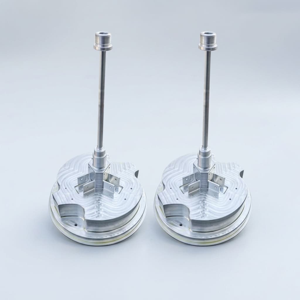
Custom Humanoid Actuator BOM Integration and Sourcing Guide
How funded robotics teams can coordinate motors, reducers, encoders, drivers, bearings, housings, harnesses, validation evidence, and export logistics through one custom actuator ODM workflow.
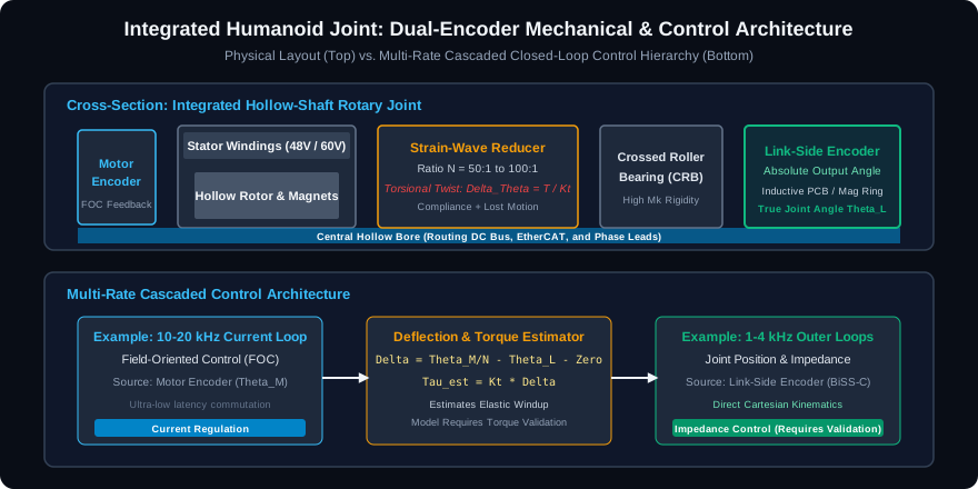
Dual-Encoder Architecture in Humanoid Joint Actuators: Link-Side vs. Motor-Side Sensing, Elastic Deflection Compensation, and RFQ Acceptance Protocols
Compare dual-encoder architecture for humanoid joints: motor vs link sensing, torque-estimation limits and calibration tests. Prepare an actuator RFQ.
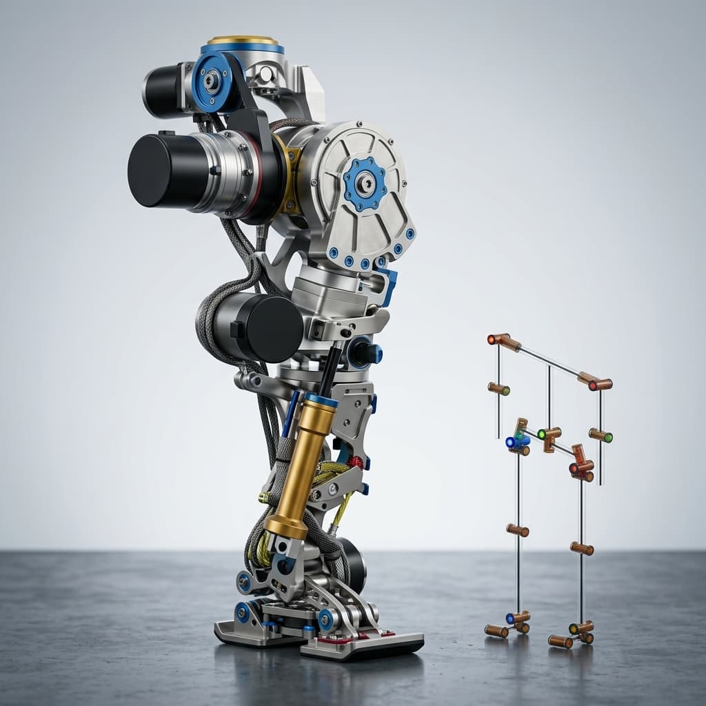
Harmonic vs. Cycloidal Drives in Custom Humanoid Actuators
Compare harmonic and cycloidal drives for humanoid robot joints. Learn how shock tolerance, backlash, and weight impact procurement and engineering decisions.