Dual-Encoder Architecture in Humanoid Joint Actuators: Link-Side vs. Motor-Side Sensing, Elastic Deflection Compensation, and RFQ Acceptance Protocols
Compare dual-encoder architecture for humanoid joints: motor vs link sensing, torque-estimation limits and calibration tests. Prepare an actuator RFQ.
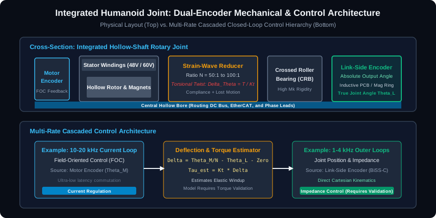
Single motor-side encoder vs. dual-encoder architecture: shortlist a single motor encoder when cost, packaging, or low transmission compliance dominates; shortlist dual encoders when load-dependent output-angle error exceeds the joint's error budget. The motor-side sensor supports commutation and rotor feedback; the link-side sensor measures the output angle after the reducer. Their difference can support elastic deflection compensation and model-based torque estimation, subject to calibration and validation.
Published and reviewed: 28 October 2026. This guide serves robotics hardware architects, mechatronics leads, and ODM sourcing teams working on custom humanoid actuators for global programs. Scope: rotary joints with a known transmission ratio and accessible output-angle sensing. Linear actuators require a separate force/displacement model. Calculations and FAT limits below are illustrative engineering proposals, not measured product results, supplier quotations, or safety certification.
Executive Sourcing & Architecture Summary
- Separate control roles: Rotor angle supports FOC; output angle supports joint position and impedance control. Current-loop execution rate and encoder sample rate are separate requirements.
- Budget residual error: Dual encoders reveal relative displacement across the measured transmission path. Backlash, friction, sensor errors, and structural flex still need an error model.
- Qualify the installed sensor: Compare inductive, magnetic, and optical designs against the actual motor current, air gap, temperature, contamination, and shock environment. No sensing principle guarantees complete system EMI immunity.
- Specify installed accuracy: Encoder bit count is resolution. Require bidirectional output-angle measurements against a calibrated angular reference, with uncertainty and residuals after calibration.
- Quote the complete change: Request the added sensor, PCB, harness, shielding, calibration time, NRE, and lead time separately. There is no universal dual-encoder cost or delivery premium.
For a technical evaluation of your joint stack, share torque-speed curves, output-angle error targets, and the mechanical envelope with our custom humanoid actuator modules engineering team.
1. The Kinematic Dilemma: When Motor-Side Feedback Is Insufficient
For an ideal rigid reducer, output angle is approximately motor angle divided by transmission ratio N. Real joints depart from that model because of torsional compliance, lost motion, bearing displacement, and housing deformation. A motor-side encoder cannot directly observe motion that occurs downstream of its mounting point.
This matters when a compact joint must position a loaded foot or hand. It does not mean every humanoid joint needs dual encoders, or that industrial arms have perfectly rigid transmissions. Make the decision against a measured output-error budget:
- Elastic windup: Obtain the selected reducer's torque-deflection curve and test it under representative loads, temperatures, and both loading directions.
- Lost motion and backlash: Measure reversing-load behavior separately from elastic stiffness. A nominal zero-backlash design can still have hysteresis and load-dependent displacement.
- Thermal and structural effects: Measure the assembled joint after warm-up. An output encoder only observes deformation within its measurement path; flex farther along a limb remains outside that path.
Reproducible sizing example: with one joint error of 0.3° and a 0.8 m perpendicular lever arm, the small-angle position error is approximately 0.8 × 0.3 × π / 180 = 0.00419 m, or 4.2 mm. This is a first-order, single-joint example. Multi-joint errors require the actual robot Jacobian and configuration; they cannot be inferred by adding generic hip and knee values.
An absolute output encoder can report angle at power-up without moving to a home switch if the joint range, retained zero, and encoder turn range are compatible. It does not by itself authorize motion: position plausibility, brakes, collision checks, and fault handling still require system validation. A multiturn motor encoder or another validated reference scheme can also support power-up position recovery.
2. Sensor Physical Principles: Magnetic vs. Inductive vs. Optical Encoders
A hollow bore may favor ring-style sensing, but the available mounting surfaces, cable route, and bearing arrangement determine the final geometry. Compare specific sensor part numbers and installation guides rather than assigning one specification to an entire technology.
2.1 Off-Axis Magnetic Ring Encoders
A magnetic ring and stationary readhead provide compact non-contact angle sensing. Field rejection varies with the ring pattern, sensor architecture, and installation. For example, the RLS AksIM-2 product page lists resolutions up to 20 bits, self-calibration, and external-field immunity features. Its stated system accuracy after encoder self-calibration is ±14 to ±72 arcseconds, depending on configuration; this is not a guarantee for a complete actuator.
Check installed angle error during current steps at multiple rotor and output positions. Do not infer local field strength or angle error from phase current alone, and do not mandate shielding solely from a fixed sensor-to-stator distance.
2.2 Planar Inductive PCB Encoders
Inductive encoders use excitation and receiver structures with a rotating target. They can be attractive near motors because they do not read a permanent-magnet scale. However, air gap, tilt, nearby conductive structures, grounding, supply noise, and inverter interference can affect a design. Require the chosen supplier's allowable geometry and verify the complete assembly; “zero effect from PWM” is not an acceptable generic claim.
2.3 Hollow-Shaft Optical Disk Encoders
Optical encoders read a patterned scale using light. They can offer high angular accuracy, but enclosure sealing, contamination tolerance, disk material, bearing alignment, and shock qualification are product-specific. Neither fragile glass nor a large cost premium applies to every optical implementation.
The following matrix is a qualitative RFQ comparison, not a measured ranking or a price list:
| Technical & Sourcing Parameter | Off-Axis Magnetic Ring | Planar Inductive PCB | Hollow-Shaft Optical Scale | Evidence to Request |
|---|---|---|---|---|
| Working principle | Magnetic scale and readhead | Excitation, receiver, and rotating target | Optical scale and readhead | Exact part number and integration drawing |
| Motor-field exposure | Field rejection depends on sensor design | No permanent-magnet scale; still qualify electrical interference | Optical sensing avoids magnetic-scale distortion; electronics still need EMC qualification | Installed angle residuals during current steps |
| Axial package | Include ring, readhead, and clearance | Include both active structure and target spacing | Include scale, readhead, and enclosure | Tolerance stack in the actuator CAD |
| Installed accuracy | Mounting and calibration matter | Gap, tilt, and surrounding geometry matter | Scale alignment and mounting matter | Bidirectional angular error map with uncertainty |
| Shock and vibration | Check hub retention and readhead alignment | Check PCB/target support and connectors | Check actual scale material and retention | Pulse shape, duration, axes, and post-test accuracy |
| Air-gap tolerance | Use the chosen ring/readhead specification | Use the chosen target/exciter specification | Use the chosen scale/readhead specification | Worst-case gap and tilt across bearing travel |
| Cost | Quote sensor plus integration | Quote sensor plus integration | Quote sensor plus integration | Volume, NRE, calibration, currency, and quote date |
| Lead time | Supplier and configuration dependent | Supplier and configuration dependent | Supplier and configuration dependent | Written prototype and production commitments |
3. High-Resolution Actuator Architecture & Closed-Loop Topology
The motor encoder measures the rotor; the link encoder measures the output flange relative to the actuator housing. Place the sensors around the transmission path whose deflection you intend to observe. The diagram shows one possible arrangement and example control rates, not a mandatory product configuration. The current controller also requires current sensing; the output-angle signal alone cannot close FOC.
Illustrative architecture. Rotor and output signals require common timestamps, a known direction convention, and a calibrated zero offset before their difference can be interpreted as deflection. Example loop rates are design inputs, not measured bandwidth.
4. Estimating Joint Torque via Transmission Deflection: Math, Models, and Real-World Limits
Dual encoders can support proprioceptive torque estimation by measuring relative angular displacement. Express both angles in radians in the same output-positive direction, unwrap motor turns before division, and use a consistent output-angle branch:
N = motor revolutions per output revolution (positive ratio magnitude)
δ = θ_motor / N − θ_link − δ_zero
τ_est = K_t × δ
Here δ_zero is the calibrated relative offset, and K_t is stiffness in Nm/rad. This convention makes positive motor advance over the output correspond to positive transmitted torque. An implementation using the opposite deflection sign must also reverse its torque convention. Unsynchronized samples can appear as false deflection during motion.
Worked example, not a hardware measurement: assume K_t = 10,000 Nm/rad, δ = 0.005 rad, and a local linear elastic model. Then τ_est = 50 Nm. If combined angular uncertainty is 0.0001 rad, its torque contribution is about 1 Nm; an additional 5% stiffness uncertainty contributes about 2.5 Nm at this operating point. These are separate sensitivity terms, not a complete uncertainty budget or demonstrated torque accuracy.
4.1 Non-Linear Piecewise Torsional Stiffness
A reducer can require different local slopes over its load range. Fit transitions and slopes to its actual torque-deflection data; do not assign universal fractions of rated torque. One continuous, symmetric illustrative model is:
d = abs(δ)
f(d) = K1 × d                                      if d ≤ d1
       K1 × d1 + K2 × (d − d1)                     if d1 < d ≤ d2
       K1 × d1 + K2 × (d2 − d1) + K3 × (d − d2)    if d > d2
τ_est = sign(δ) × f(d)
K1, K2, and K3 are slopes in Nm/rad, not polynomial coefficients. The sign term handles negative loading and the accumulated terms keep the curve continuous. This model excludes hysteresis; characterize positive and negative loading/unloading paths separately if those differences matter.
4.2 The Stiction and Hysteresis Blind Spot
Friction, hysteresis, bearing loads, and encoder errors limit how well displacement predicts torque, particularly near load reversal. Validate against a calibrated reaction torque transducer over the intended load, speed, direction, and frequency range. A static stiffness fit cannot establish dynamic torque bandwidth or collision-detection performance. Dedicated torque sensors have their own uncertainty, overload, thermal, and packaging limits and may be preferable for low-force tasks.
4.3 Temperature Sensitivity of Flexspline Compliance
Temperature can change effective stiffness, friction, sensor offsets, and the mechanical mounting stack. Repeat the torque-deflection test after thermal stabilization at the agreed operating points. Record where temperature is measured and validate any compensation outside its fitted data. Do not infer a universal percentage drift from steel properties alone.
For an architecture review, send these assumptions with your joint integration requirements, including whether torque is an estimate for control or an independently verified measurement requirement.
5. Mechanical Runout, Eccentricity, and 1P Harmonic Error Calibration
A 20-bit encoder provides 1,048,576 counts per revolution: 360 × 3600 / 2^20 ≈ 1.236 arcseconds per count. Resolution is not installed accuracy; scale errors, mounting, temperature, and calibration all contribute.
5.1 The Fundamental Eccentricity Formula (1P Error)
For an ideal circular scale with a single local readhead and small eccentricity e relative to track radius R, a first-order geometric model gives:
angular error(φ) ≈ (e / R) × sin(φ − φ_zero) radians
peak error amplitude ≈ e / R
This is a screening model, not a universal error equation for magnetic or inductive sensor processing. Eccentricity is the offset of centers; for pure eccentricity, radial total indicated runout (TIR) is approximately 2e. Do not enter a TIR limit as e without checking its definition. Track radius also differs from the component's outer radius.
| Illustrative Eccentricity e | Reading Track Radius R | Peak Angular Error | Peak Angular Error in Arcseconds |
|---|---|---|---|
| 10 µm | 35 mm | 0.000286 rad | 58.9 |
| 25 µm | 35 mm | 0.000714 rad | 147.3 |
| 50 µm | 35 mm | 0.001429 rad | 294.7 |
| 25 µm | 20 mm | 0.001250 rad | 257.8 |
| 10 µm | 20 mm | 0.000500 rad | 103.1 |
| 5 µm | 35 mm | 0.000143 rad | 29.5 |
These values are calculated from e / R × 180 / π × 3600. They are peak amplitudes, not peak-to-peak values, measured results, or a reduction in the encoder's digital bit count.
5.2 Mitigation: Dual-Readhead Cancellation vs. Factory LUT Calibration
- Opposed readheads: Averaging appropriately aligned and unwrapped readhead angles can cancel first-order eccentricity in the ideal symmetric arrangement. Readhead mismatch, even harmonics, and mounting errors remain; verify residuals rather than assuming perfect cancellation.
- In-situ calibration: Compare the completed actuator with a calibrated angular reference over its operating travel, in both directions. Record the zero, load, speed, temperature, reference uncertainty, and angular sampling. Fit a correction Look-Up Table (LUT) and verify residuals at independent angles. A LUT corrects repeatable errors within its validation conditions; it cannot remove variable backlash or changing structural deformation.
Require a serialized calibration file, firmware/configuration revision, pre/post correction maps, and recalibration rules after encoder, bearing, or reducer replacement. Encoder self-calibration and full assembled-joint calibration are different deliverables.
6. Real-Time Deterministic Bus Protocols: BiSS-C vs. SSI vs. SPI vs. EnDat
Separate the local sensor-to-drive interface from the robot's drive network. A robot may use EtherCAT between drives while using BiSS-C or SPI inside each actuator. Twenty robot joints do not imply that twenty encoders share one local serial chain.
6.1 BiSS-C (Bidirectional Serial Synchronous, Continuous Mode)
The BiSS Association downloads provide the protocol description, encoder profiles, CRC guidance, and master implementation notes. Specify the supported sensor/master profile, electrical layer, cable, clock, data length, and CRC configuration together. Ordinary BiSS-C and BiSS Safety have distinct requirements; CRC detection does not establish functional safety.
Serialization example: a 24-bit position word plus 2 status bits and 6 CRC bits totals 32 bits. At an assumed 10 MHz clock, those bits take 32 / 10,000,000 = 3.2 µs. Total sample-to-controller latency additionally includes acquisition/filter delay, protocol overhead and timeout, propagation, master processing, and scheduling. Measure it at the actual configuration; 3.2 µs is not a complete BiSS-C cycle or a guaranteed control latency.
6.2 SSI (Synchronous Serial Interface)
SSI implementations vary in word length, status information, and vendor extensions. Do not assume a particular integrity mechanism. Request the actual frame definition, maximum cable/clock combination, detection of stale or invalid data, and the controller response to faults.
6.3 SPI (Serial Peripheral Interface)
SPI is often useful within an actuator PCB. Its permitted interconnect length depends on clock speed, signal integrity, grounding, level translation, and the physical driver. Validate the intended harness; there is no universal 50–100 mm cutoff and no blanket requirement to use one rigid-flex PCB.
6.4 EnDat
If evaluating EnDat, compare the chosen encoder and receiver version, diagnostics, timing, integration effort, and any applicable safety documentation. An interface name alone establishes neither a safety rating nor a cost disadvantage. Ask suppliers to quote a supported implementation.
7. Joint-by-Joint Sourcing Trade-Off Matrix
Use the following matrix to start a design review. It covers rotary joint concepts; it does not prescribe a safe architecture from joint name alone. Torque envelopes and costs must come from the robot load case and written quotations.
| Joint Placement | Main Engineering Question | Feedback Shortlist | Sensor Qualification Priority | Torque-Estimate Limitation | Procurement Decision Evidence |
|---|---|---|---|---|---|
| Ankle pitch & roll | Does loaded output-angle error exceed the foot-placement budget? | Evaluate dual feedback for compliant reducers | Shock, retention, gap, and current exposure | Impact dynamics require validation beyond a static fit | Loaded output-angle and transient torque records |
| Knee pitch | Is windup significant under squat and landing loads? | Compare dual feedback with a validated single-sensor model | Warm-up, load reversal, and bearing deflection | Friction and changing load path bias estimates | Bidirectional load/temperature map |
| Hip pitch & roll | How much does joint error shift pelvis/foot pose? | Evaluate output sensing against the kinematic budget | Installed angle accuracy and timestamps | Housing flex outside the sensed path is unobserved | Robot Jacobian error allocation plus joint tests |
| Hip yaw / torso turn | Is reducer compliance material at the intended load? | Single or dual, based on measured residual error | Cable routing and rotational range | Low-load hysteresis can dominate | Bench measurements under reversing load |
| Shoulder & elbow | Is precise loaded positioning or contact control required? | Evaluate dual encoders and dedicated torque sensing | Mass, thermal drift, and magnetic environment | Deflection estimation alone is not a safety function | Task-specific force/torque validation |
| Wrist / neck | Does extra sensing improve a measurable task requirement? | Single may suffice; dual if accuracy requires it | Packaging and output resolution/accuracy | Small deflection can be below reliable observability | Error budget and fully costed integration quote |
8. Quality Inspection & Factory Acceptance Test (FAT) Matrix
Agree the following plan before the sample purchase order. All numerical limits in this table are proposed examples, not industry standards or demonstrated capabilities. Buyer and supplier must confirm feasibility, reference uncertainty, sample count, operating points, and pass/fail rules. Environmental qualification may use designated samples; define which checks run on every production unit.
| Inspection Test Protocol | Measured Parameter | Example Acceptance Proposal | Test Setup & Required Record | Engineering Decision |
|---|---|---|---|---|
| 1. Absolute angular accuracy | Maximum signed output error and repeatability | Example: absolute error no greater than 45 arcseconds after calibration | Calibrated rotary reference; both directions; independent angles across travel; fixed load and temperature; uncertainty and guard-band decision rule | Confirm installed accuracy against the joint budget |
| 2. Torque-deflection map | Local stiffness and loading/unloading hysteresis | Example: fitted stiffness within ±7% of the agreed baseline at specified loads; define a separate torque-error limit | Calibrated reaction torque transducer; synchronized angles; load sweeps in both directions and at agreed temperatures | Decide whether estimated torque is useful for the task |
| 3. Current-induced angle error | Change from a reference angle while energized | Example: added angle error no greater than 0.015° over the agreed current profile | Secured fixture and angular reference; continuous current within thermal rating, peak pulses within rated duration; separate physical motion from sensor error | Qualify field rejection and electrical integration |
| 4. Thermal position drift | Zero shift and angle error after stabilization | Example: zero shift no greater than 0.03° over an agreed temperature span inside component ratings | Chamber plus reference; record sensor/housing temperatures, dwell, load, and repeatability | Validate compensation and warm-up limits |
| 5. Shock qualification | Retention, fault logs, and post-shock angle error | Example screening pulse: 30 g, 6 ms half-sine; agree axes, pulse count, mounting, and post-test angular limit | Instrumented shock fixture; before/after calibration; visual and connector inspection | Qualify the actual assembly, without claiming gait or safety certification |
| 6. Communication integrity | CRC/status faults, stale data, and end-to-end latency | Example: no observed CRC faults in 10 million frames at the agreed clock; inject faults and verify the specified response | Actual cable and inverter conditions; protocol capture plus independent timing; record denominator and all invalid frames | Validate detection and recovery; a finite zero-error run does not prove zero error probability |
9. 10-Point Engineering & Procurement Checklist for Dual-Encoder RFQs
Before releasing an RFQ, turn these questions into agreed drawing and acceptance requirements:
- 1. Sensor resolution and installed accuracy: Specify each channel separately, including angular range, absolute/multiturn behavior, and residual error after calibration.
- 2. Physical architecture: Identify the sensing technology, exact part number or approved alternatives, mounting arrangement, and interference test conditions.
- 3. Hollow-bore clearance: Define usable bore diameter, cable bend radius, connector envelope, and interference over full travel.
- 4. Datums and tolerances: Define eccentricity versus TIR, axial endplay, and readhead gap/tilt. A diameter fit class alone does not control runout.
- 5. Calibration handoff: Request serialized correction files, reference traceability, uncertainty, firmware revision, and raw plus corrected maps.
- 6. Protocol and timing: Specify electrical interface, frame/status/CRC settings, clock, cable, timestamps, maximum data age, and fault response.
- 7. Torque model: Agree units, sign, offsets, fitted stiffness regions, temperature range, hysteresis treatment, and validation against a torque reference.
- 8. Thermal and field exposure: State continuous/peak current with duration, PWM conditions, housing temperature, and shielding validation if needed.
- 9. Environment and service: Define shock pulse/axes/count, vibration, sealing requirements, maintenance, and recalibration after component replacement.
- 10. Commercial and quality deliverables: Request dated volume quotes, NRE/tool ownership, sample schedule, production test coverage, traceability, and change-control terms.
10. Frequently Asked Questions (FAQ)
Can dual encoders completely eliminate mechanical backlash in humanoid joints?
No. They can reveal relative displacement across the measured transmission path and support compensation, but physical clearance, friction, and hysteresis remain. Validate output tracking during reversing loads and tune the controller against the real mechanical system.
Why use a dedicated torque sensor instead of dual-encoder deflection estimation?
Choose based on required torque uncertainty, bandwidth, low-force behavior, overload limits, packaging, and cost. Deflection estimation depends on sensor timing and a validated stiffness/friction model. Dedicated torque sensors also need calibration and thermal qualification. Neither architecture alone establishes safe contact performance.
What causes magnetic ring encoder angle errors when motor current changes?
External fields and electrical interference can affect some installations, while ring and readhead designs differ in rejection capability. Current alone does not predict local field or error. Compare sensor output against an independent angular reference during rated current steps at several rotor positions, separating actual mechanical movement from sensing error.
Are planar inductive encoders always better than magnetic rings in bipedal legs?
No. Compare the selected parts against available space, mounting gap and tilt, installed accuracy, shock and vibration, temperature, contamination, and motor interference. Inductive sensing avoids a permanent-magnet scale, but it still requires electrical and mechanical qualification in the assembled joint.
What communication latency is acceptable for a link-side BiSS-C encoder?
Derive the limit from control stability, sensor filtering, loop timing, synchronization, and maximum permitted data age. At an assumed 10 MHz clock, 32 data/status/CRC bits take 3.2 microseconds to serialize. Acquisition, protocol overhead, timeout, propagation, and scheduling add latency. Specify and measure the complete sample-to-controller path.
11. Moving from Sizing to Integrated ODM Prototypes
For a custom humanoid actuator inquiry, request a configuration-specific proposal covering rotor/output sensors, reducer, bearing arrangement, drive interface, calibration, and FAT deliverables. Confirm supported hardware and validation coverage in writing rather than treating an architecture illustration as a standard product specification.
If your team is finalizing joint specifications for bipedal legs, torso assemblies, or manipulators:
- Review integration options for custom humanoid actuator modules.
- Explore packaging choices for compact humanoid arm actuators.
- Evaluate cable routing in frameless hollow-shaft humanoid actuators.
- Send torque-speed curves, output-angle and torque-error targets, CAD envelope, quantity, and required test records through our engineering inquiry page.
12. Sources & Authoritative References
Reference review date: 28 October 2026. Official publisher pages below provide protocol and product documentation. The linked PDFs are listed by those publishers; numerical procurement examples and calculations in this guide are our proposed analysis, not results reported by these sources. Confirm the document revision and selected part number when freezing an RFQ.
- BiSS Association — Official protocol and application-note downloads. The index identifies protocol descriptions, encoder profiles, CRC application notes, and separate BiSS Safety material. It does not certify a complete robot joint.
- BiSS Association — BiSS C Protocol Description, English (PDF). Protocol document linked from the official download index; use it with the selected encoder profile and master implementation guidance.
- RLS — AksIM-2 off-axis rotary absolute magnetic encoder. Product-specific resolution, self-calibration accuracy, interface options, environmental limits, and documentation; these specifications do not characterize every magnetic encoder.
- RLS — AksIM-2 data sheet MBD01 (PDF). Installation and configuration reference linked from the product page. Obtain the applicable revision before committing mechanical tolerances.
- RLS — Torque measurement with AksIM (PDF). Further reading listed on the product page for torque-measurement applications; it is not evidence of this site's actuator test performance.
Author

Categories
More Posts

Inverted Planetary Roller Screws vs. Ball Screws in Humanoid Linear Actuators: Sourcing, Dynamic Load, and Life-Cycle Engineering
Compare inverted planetary roller screws vs ball screws for humanoid actuators. Check loads, life assumptions and RFQ evidence before requesting a quote.
How to Source Custom CNC Housings for Humanoid Actuators
An engineering breakdown of tolerances, material selection, GD&T, and machining costs when moving from benchtop prototype actuators to pilot-production precision CNC housings.
Custom Humanoid Actuator BOM Integration and Sourcing Guide
How funded robotics teams can coordinate motors, reducers, encoders, drivers, bearings, housings, harnesses, validation evidence, and export logistics through one custom actuator ODM workflow.