Inverted Planetary Roller Screws vs. Ball Screws in Humanoid Linear Actuators: Sourcing, Dynamic Load, and Life-Cycle Engineering
Compare inverted planetary roller screws vs ball screws for humanoid actuators. Check loads, life assumptions and RFQ evidence before requesting a quote.
Inverted planetary roller screws vs. ball screws: shortlist an inverted roller screw when the required force and stroke are difficult to package; shortlist a ball screw when a catalog assembly meets the load, motion and service requirements. Neither architecture guarantees shock survival or a particular operating life. Compare identified part numbers against the same linkage, duty cycle and acceptance tests.
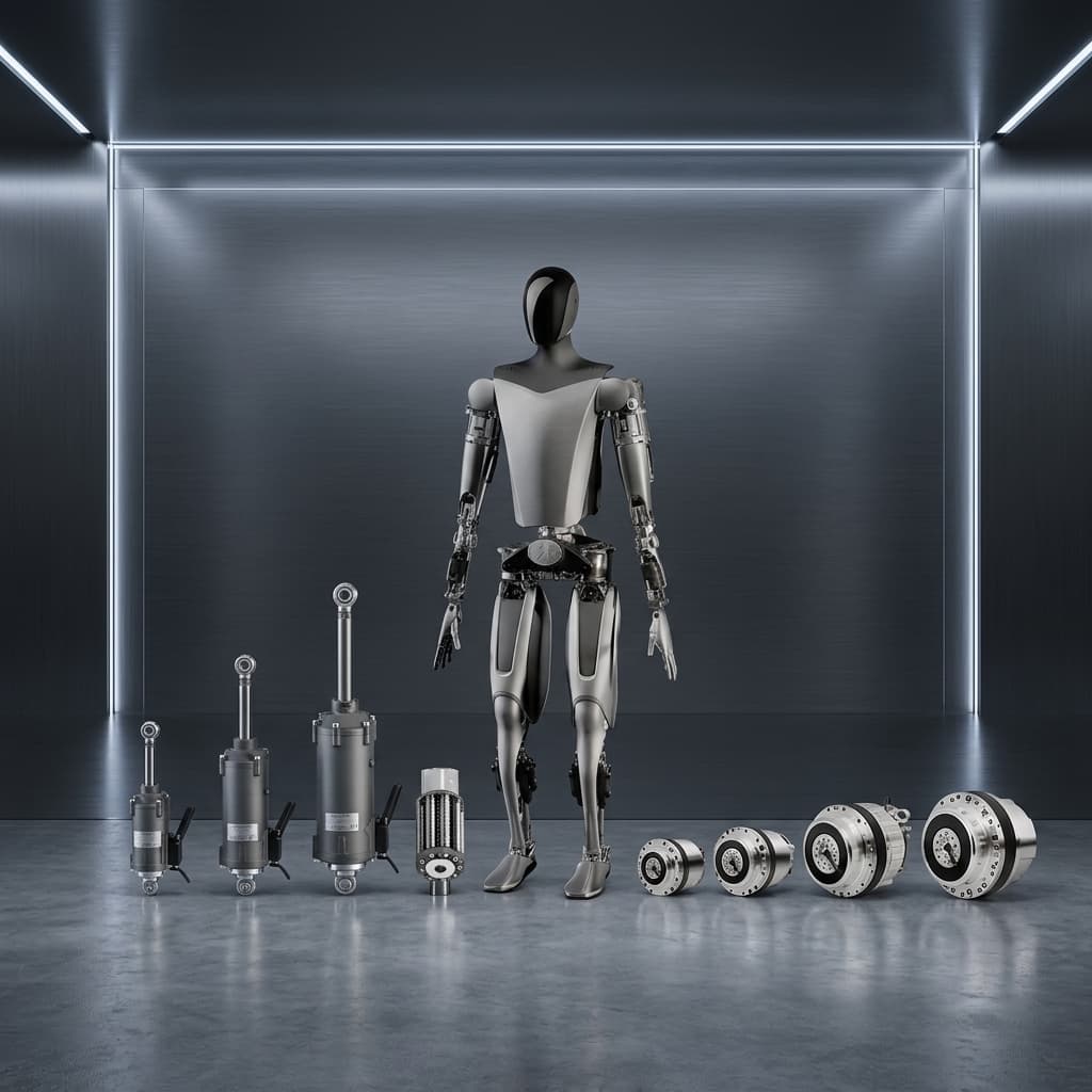
Published and technically reviewed: 26 October 2026. This English-language guide supports global OEM engineering and procurement teams comparing humanoid linear actuators. It covers mechanical selection and RFQ preparation; it does not certify a robot, supplier or safety function. Catalog information and the illustrative calculation below are distinct from physical test results. The cover is a concept illustration, not a tested product or customer installation.
Executive Sourcing Summary
- Load first: Convert joint torque into screw force across the full linkage travel, then check fatigue loading and stationary or impact loading separately.
- Packaging second: Compare complete assemblies including motor, bearings, anti-rotation guide, seals and end stops. There is no universal percentage length saving from an inverted layout.
- Comparable quotes: Request the same preload, inspection scope, quantity and duty cycle. Cost and lead time require dated supplier quotations.
- Release evidence: Require the supplier's life method and application-specific shock, thermal and short-stroke tests before production approval.
For a design review, share your force-stroke targets with our humanoid linear actuator integration team. The comparison below helps define the evidence to request before choosing a transmission.
1. When Linear Pushrods Fit a Humanoid Joint
A linear pushrod can drive a knee, ankle or other linkage while placing motor mass away from the joint pivot. Whether this reduces distal inertia or improves packaging depends on the complete arrangement.
For a planar linkage, start with joint torque = axial force × perpendicular moment arm. Calculate that moment arm at every joint angle. Near a linkage singularity, a small moment arm can demand a large screw force even when joint torque has not increased. A straight knee does not automatically provide favorable leverage.
Model ground-contact loads through the leg geometry and structural compliance. Robot mass or body acceleration in g alone cannot specify force inside an individual screw. Include tension, compression, side loads, emergency stops and the duration of each peak.
2. Contact Mechanics: Ball Contacts and Roller-Thread Contacts
Ball screws transmit force through balls contacting the screw and nut raceways. Roller screws distribute force through multiple engaged roller threads. Both have finite elastic contact patches under load; the familiar point-contact versus line-contact sketch is a simplification.
Conceptual contact comparison, not a Hertzian analysis or test result. Patch size and stress require the actual geometry, material, preload and load sharing.
Avoid deriving a fixed load multiplier from this drawing. Overload can permanently indent either mechanism. Compare the supplier's dynamic axial rating (Ca) and static axial rating (C0a), and ask how they were established for the selected assembly.
The Ewellix roller screw catalog, calculation section distinguishes fatigue rating from service life and highlights stationary shock loading and external guidance. The RFQ implications below are an engineering screening framework, not measured comparisons between two products.
3. Fundamental Mechanical and Kinematic Comparison
Use this matrix to request comparable evidence rather than assign a winner from the mechanism name.
| Engineering parameter | Precision ball screw | Conventional planetary roller screw | Inverted planetary roller screw | RFQ decision |
|---|---|---|---|---|
| Load transfer | Balls and raceways | Multiple roller-thread contacts | Multiple roller-thread contacts in an inverted arrangement | Obtain part-specific Ca and C0a; do not assume a fixed ratio. |
| Fatigue rating | Check the ball-screw method | Check the manufacturer's method | Check the exact inverted-series method | Compare the same duty cycle, reliability basis and units. |
| Impact loading | Must meet the specified event | Must meet the specified event | Must meet the specified event | Review peak force, duration, deformation limits and support bearings. |
| Lead and speed | Available diameter/lead combinations | Series-dependent combinations | Series-dependent combinations | Check linear speed, input speed, buckling and motion limits together. |
| Efficiency and preload | Depends on lead, preload, seals and lubrication | Depends on geometry and operating point | Depends on geometry and operating point | Request drive and backdrive torque maps at the required temperatures. |
| Axial packaging | Rotating-screw or rotating-nut options | Evaluate full motor and support arrangement | Extended nut and roller arrangement can suit integration | Compare CAD at both stroke limits, including end stops and guides. |
| Side loads | Provide suitable external support | Provide suitable external support | Provide suitable external support | Define permitted misalignment and the guide's load responsibility. |
| Sourcing and service | Catalog or custom assembly | Specialized series or custom assembly | Specialized series or custom assembly | Obtain dated quotes, replacement terms and qualified alternatives. |
4. Inverted Planetary Architecture: Mechatronic Integration in Limbs
An inverted design changes the roller arrangement and uses an extended internally threaded nut. The word "inverted" alone does not identify which member rotates, which translates or how the roller set is retained. Conventional roller screws can also use rotating-nut arrangements. Request a supplier cross-section and motion description before designing the motor interface.
The illustration assumes a rotating nut and translating screw output. It shows integration interfaces only; it omits the detailed thread mesh and roller retention required for a production mechanism.
Illustrative rotating-nut layout, not a manufacturing drawing. Confirm actual roller travel, retention and clearance throughout the stroke.
A directly integrated rotor can remove a shaft coupling, but the assembly still needs a thrust-bearing load path, anti-rotation support, sealing and a tolerance stack. Bearing and housing deflection remain finite and can affect the motor air gap. Review custom actuator housings and interfaces with the supplier's loads and interface drawings.
5. Fatigue Life Calculation: Use the Supplier's Screw Model
The ISO 3408-5:2006 catalog entry identifies a method for ball-screw axial ratings and life. Its public scope does not establish a roller-screw rating. A roller bearing's life exponent must not be transferred automatically to a roller screw.
For example, the cited Ewellix roller screw catalog uses a cubic basic life model. Using that model for an illustrative screening calculation:
L10 [revolutions] = (Ca / Fm)^3 × 1,000,000 Fm = (sum(Fi^3 × di) / sum(di))^(1/3)
Ca is the catalog dynamic axial rating, Fi is a positive axial load magnitude and di is the travel distance in that segment. For constant lead, distance weighting corresponds to revolution weighting. A variable-speed time record needs speed/travel weighting, not a simple time average. Reversals, preload and load direction need the supplier's specified treatment.
Reproducible example: why the arithmetic mean can mislead
Assume two moving-load segments: 1,000 N for 80% of travel and 4,000 N for 20%. Assume a hypothetical Ca of 10,000 N and the cubic model, with no preload or correction factors:
- Cubic equivalent load: Fm = (0.8 × 1,000³ + 0.2 × 4,000³)^(1/3) ≈ 2,387 N.
- Basic life: (10,000 / 2,387)³ × 1,000,000 ≈ 73.5 million revolutions.
- An arithmetic mean of 1,600 N would give about 244.1 million revolutions, overstating this modeled result by about 3.3 times.
These are synthetic inputs, not a catalog selection or hardware life claim. L10 is a statistical fatigue rating, conventionally associated with 90% survival under the model assumptions; it is not a service-life warranty. Convert revolutions to hours with the actual motion schedule. Loaded dwell, impacts, corrosion and short-stroke wear need separate assessment even when they add little travel to the fatigue sum.
Ask each supplier to return the calculation method, catalog revision, load spectrum, preload treatment, reliability basis and exclusions. Compare quoted hours only after those assumptions match. An FEA and thermal engineering review can assess the surrounding structure and heat path; it does not replace the screw manufacturer's rating method or endurance testing.
6. Micro-Dithering, Fretting and Lubrication
During loaded standing, a controller may repeatedly reverse the actuator over a short distance. Controller update frequency is not physical oscillation frequency. Record actual pushrod displacement, force, temperature and reversal frequency before specifying a test.
NSK's false-brinelling guidance identifies small oscillations, vibration and poor lubrication as causes of bearing wear marks. This explains a relevant rolling-contact risk; it does not establish a failure threshold for a particular screw.
Agree on a loaded short-stroke test using the intended lubricant, seals, temperature range and assembly preload. Measure drag torque, backlash and surface condition before and after testing. Include loaded dwell and representative transport vibration when relevant.
A universal grease viscosity, additive package, coating or periodic 15 mm sweep cannot be prescribed from this comparison. Lubricant compatibility and any redistribution motion need supplier approval and validation within the robot's balance and collision constraints. Coating or lubricant changes also require renewed clearance and friction checks.
7. Joint Kinematic Allocation Matrix Across the Humanoid Body
These are candidate-selection questions, not published load or stroke specifications for production robots. Each joint can use other transmission architectures.
| Joint location | Linear mechanism candidate | Main selection question | Evidence before selection |
|---|---|---|---|
| Knee pitch | Ball screw or inverted roller screw with pushrod linkage | Can it meet force at the smallest moment arm and both stroke limits? | Linkage force map, compression buckling check and loaded cycle test. |
| Ankle pitch | Single or paired pushrods | Can it tolerate contact loads while maintaining foot clearance? | Impact spectrum, guide loads and assembly deflection. |
| Ankle roll | Differential pushrod pair | How are load sharing and actuator mismatch handled? | Coupled linkage analysis and reversal/feedback tests. |
| Hip pitch | Linear assist or primary pushrod | Does the package improve the complete hip layout? | Full-range interference, thermal and holding-load assessment. |
| Elbow or wrist | Compact ball or roller screw | What friction and backlash are acceptable for manipulation? | Measured breakaway force, drive/backdrive curves and lost motion. |
| Hand or fingers | Miniature screw or tendon stage | Can the mechanism fit and remain serviceable? | Tendon/guide load path, contamination and small-stroke wear checks. |
8. Sourcing Realities: Cost, Lead Time and Manufacturing Precision
Ball screws have catalog options across many suppliers, while an inverted roller screw may require a more specialized source. Neither statement establishes a price or delivery date. Grinding, preload, internal thread access, gauging and sample approval can affect a custom quote.
Send both candidates the same drawing revision, quantity, force-speed envelope, inspection requirements and delivery destination. Request dated prototype and pilot quotations, separating bare screw/nut cost from motor, bearing, guide, housing, tooling, inspection and integration cost. Record quote validity, currency and commercial terms for global comparisons.
For life-cycle cost, add planned lubrication/service, replacement access, spare availability and requalification effort to acquisition cost. Calculate this from your own expected service schedule rather than assuming an industry-wide saving.
A second source is qualified only after its interfaces, load method, preload, lubricant and acceptance results have been compared. Similar diameter and lead do not establish interchangeability.
9. Technical Procurement & RFQ Acceptance Specifications
Set application limits and agree them before ordering. Diameter alone cannot establish a required load rating or impact survival.
| RFQ acceptance parameter | What to specify | Verification evidence | Procurement purpose |
|---|---|---|---|
| Lead accuracy | Permitted travel error over useful stroke and temperature | Identified method and calibrated travel-error report | Make positioning requirements measurable. |
| Backlash and stiffness | Reversal force, preload, temperature and measurement locations | Force-displacement and reversal curves | Separate clearance from elastic deflection. |
| Dynamic axial rating | Required model-based life under the agreed load spectrum | Supplier calculation with Ca, method and correction factors | Compare fatigue assumptions. |
| Static and shock loading | Peak magnitude, duration, repetitions and permissible permanent set | Static-margin review and agreed instrumented assembly test | Assess exceptional load events separately from fatigue. |
| Drag and backdrive torque | Limits across stroke, speed and temperature | Measured torque traces with seals and lubricant installed | Check controller and thermal assumptions. |
| Bearings and alignment | Datum scheme, fits, runout and allowed deflection | Metrology and loaded assembly checks | Protect the screw mesh and motor air gap. |
| Guides and anti-rotation | Side-load/moment envelope and clearance limits | Loaded guide and full-stroke tests | Keep transverse loads out of the screw contact path. |
| Materials and lubrication | Material, heat-treatment profile, approved lubricant and traceability | Material records and agreed inspection reports | Control substitutions and production consistency. |
10. 10-Point Engineering & Procurement Checklist for Linear Actuator RFQs
- 1. Linkage profile: CAD, joint-angle range, moment-arm curve and full stroke.
- 2. Moving duty cycle: Signed force, velocity and position records for intended tasks.
- 3. Exceptional loads: Shock force, duration, repetitions, emergency-stop and loaded-dwell cases.
- 4. Package and guidance: Retracted/extended envelope, side loads, guide and anti-rotation responsibilities.
- 5. Architecture definition: Identified series, diameter, lead, preload, rotating member and output interface.
- 6. Motor boundary: Bus voltage, current limits, torque-speed envelope, holding duty and heat path.
- 7. Feedback: Motor and output sensing, required accuracy, protocol and compliance compensation.
- 8. Lubrication: Approved lubricant, temperature/environment limits, short-stroke test and service plan.
- 9. Acceptance evidence: Agreed travel error, lost motion, torque, thermal, shock and endurance criteria.
- 10. Commercial baseline: Sample/pilot quantities, dated delivery commitment, tooling ownership, spares and change control.
11. FAQ: Linear Actuators in Humanoid Robotics
Can ball screws be used in humanoid knee joints?
Yes, if the identified assembly meets the linkage force, fatigue life, static load, shock, stiffness and packaging requirements. An inverted roller screw is a candidate when those requirements are difficult to meet in the available envelope. Joint location alone does not decide the mechanism.
What distinguishes a conventional roller screw from an inverted roller screw?
An inverted design changes the roller arrangement and uses an extended internally threaded nut. The supplier drawing must identify the rotating member, translating output, roller retention and stroke limits. A rotating nut alone does not establish that the screw is inverted.
Can inverted roller screws backdrive for compliant humanoid control?
Backdriving depends on lead, preload, seals, lubricant, temperature, motor and any brake. Request breakaway and backdrive torque measurements for the complete assembly. A nominal efficiency figure alone cannot establish compliant control or safe holding behavior.
How should micro-dithering during standing be validated?
Measure actual loaded displacement and reversal frequency, then agree a short-stroke and dwell test with the screw supplier. Use the intended lubricant and temperature range and compare torque, backlash and surface condition before and after. Validate any redistribution motion within robot balance and collision constraints.
What lead time should teams budget for custom inverted roller screw prototypes?
Use a dated supplier commitment for the exact series, interfaces, preload, quantity and inspection scope. Ask separately about tooling, sample approval and pilot capacity. A generic week range cannot predict delivery of a custom assembly.
12. Moving from Sizing to Integrated ODM Prototypes
Custom Humanoid Actuator supports application review and integration of screws, motors, sensors, guides and housings around a defined force-stroke-duty envelope. The exact sourcing, manufacturing and test scope is agreed for each program; this article does not represent a qualification record for a specific screw.
If you are preparing a knee, ankle or other linear-joint RFQ, send the checklist, CAD envelope, duty cycle, quantities and target date through our contact page. Start with humanoid linear actuator integration if the transmission choice is still open.
13. Sources & Authoritative References
Reference review date: 26 October 2026. Sources support the stated scope; the matrices and worked example are engineering screening aids, not supplier test evidence.
- ISO 3408-5:2006 — Ball screws: static and dynamic axial load ratings and operational life. ISO catalog record. Used to identify the standard's scope; the public abstract is not the full normative text.
- Ewellix — Roller screws, publication IL-05003/1-EN, June 2020. Manufacturer catalog, public distributor-hosted PDF. See the basic life, equivalent load and service-life calculation sections. This dated edition is a method reference, not confirmation of current stock or specifications; obtain the applicable revision for the quoted series.
- NSK — False Brinelling. Manufacturer bearing-damage guidance. Supports the small-oscillation and lubrication risk discussion for rolling contacts; it does not rate a humanoid screw or establish a universal grease specification.
Author

Categories
More Posts
Frameless vs. Framed Motors in Humanoid Robot Joints: A Packaging and Thermal Analysis
An in-depth engineering analysis on why advanced humanoid robot teams migrate from framed servomotors to frameless torque motors for custom joint actuators to optimize space, weight, and thermal dissipation.
Standardized Evaluation Protocols for Humanoid Actuator Procurement
2026 procurement guide for custom humanoid actuator FAT/SAT protocols, dynamic-load tests, thermal derating, source evidence, and RFQ acceptance limits.
Humanoid Actuator Backlash Testing: RFQ Guide for Custom Reducers
How to evaluate reducer backlash claims for custom humanoid actuators, including preload, reversal method, assembled-joint testing, encoder location, and pilot-batch evidence.