
Custom Humanoid Actuator logoCustom Humanoid Actuator
Start inquiry
Custom Humanoid Actuator logoCustom Humanoid Actuator
WhatsApp
Custom Humanoid Actuator logoCustom Humanoid Actuator

Custom humanoid actuator ODM manufacturing for funded robotics teams, from drawings and prototypes to pilot batches.

Inquiry Email

[email protected]

Email app

Include target torque/speed, quantity, and delivery location.

Application Engineer

+8618857971991

Talk on WhatsApp

Talk directly about drawings, torque-speed targets, and RFQ data gaps.

Products
  • Custom Humanoid Actuator Modules
  • Custom QDD Humanoid Actuators
  • Custom Humanoid Leg Actuators
  • Compact Arm and Wrist Actuators
  • Humanoid Linear Actuator Integration
  • Dexterous Hand Micro Actuators
  • Frameless Hollow Shaft Actuators
  • Custom Reducer Architectures
  • Custom Actuator Housings
Solutions
  • Funded Humanoid Prototype Programs
  • Bipedal Leg Custom Joints
  • Humanoid Arm and Hand Actuation
  • Nonstandard Robot Envelopes
  • Pilot to Mass Production Actuators
OEM Capabilities
  • Drawing-to-Production ODM
  • FEA and Thermal Engineering Review
  • Precision Machining and Metrology
  • BOM Supply Chain Integration
  • Prototype and Pilot Production Control
  • Quality and Engineering Validation
  • Export Packaging and Global Delivery
Resources
  • Engineering Resources
  • Humanoid Robot Guide
  • Sample RFQ Package
  • Evidence Library
  • Test Plan Checklist
  • Backlash Acceptance Method
  • Sample PO Checklist
  • Pilot Readiness Checklist
  • Blog
  • About
  • Contact / RFQ
  • Privacy Policy
  • Cookie Policy
  • Terms of Service
© 2026 Custom Humanoid Actuator. All Rights Reserved.|Custom Humanoid Actuator is operated by Linkup Ai Co., Ltd. Manufacturing support is coordinated through Linkup Precision's advanced manufacturing division.
Legal entity: Linkup Ai Co., Ltd.
← Back to Products

Humanoid Linear Actuator Integration

Custom integration support for humanoid linear actuators using roller screw, lead screw, ball screw, pushrod, or compact linkage-driven architectures where force, stroke, guide support, backlash, side load, and heat rise must be validated together.
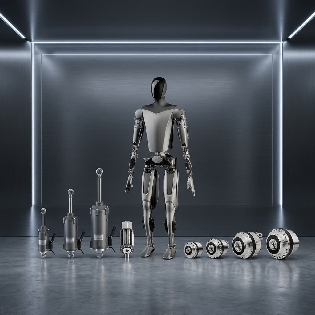
Target Buyer:For humanoid teams that need custom linear motion hardware where rotary catalog joints cannot meet stroke, force, or packaging requirements.
Send CAD for RFQ ReviewCheck RFQ Baseline
humanoid linear actuator integration overview

Custom Program Fit, Not Standard Model Browsing

This page should help a robotics buyer decide whether this product family belongs in the RFQ path and what evidence must be attached before a prototype or pilot order is credible.

Who this fits

For humanoid teams that need custom linear motion hardware where rotary catalog joints cannot meet stroke, force, or packaging requirements.

First engineering metric

Stroke-force envelope: Finger pushrod to leg-assist dependent

Pilot risk to control

Miniature screw assembly binds under side load

Capability Highlights

  • Miniature and high-load linear actuator packaging for fingers, hands, pushrod joints, and linkage systems
  • Screw, nut, motor, sensor, guide rail, housing, bearing, and cable integration around real stroke-force-duty targets
  • Manufacturing review for ground screws, roller screw or ball screw sourcing, nut assemblies, anti-rotation features, and compact actuator housings

Typical Applications

  • Humanoid hand and finger actuation
  • Compact linear joints and linkage mechanisms
  • Robot pushrod and tendon-assist subsystems

Best-Fit Buying Signals

  • Humanoid hand and finger actuation
  • Miniature and high-load linear actuator packaging for fingers, hands, pushrod joints, and linkage systems
  • Convert force, stroke, speed, duty cycle, backlash target, allowable side load, and heat path into a manufacturable screw or linkage architecture

Redirect the RFQ If

  • Architecture still undecided: Compare QDD, harmonic, cycloidal, planetary, linear, and hybrid reducer paths before freezing the actuator drawing.
  • Only the mechanical housing is in scope: Route the inquiry to precision housings, bearing seats, flanges, shafts, datum control, and inspection evidence.
  • No RFQ baseline exists yet: Build the first-pass package around CAD, torque-speed, duty cycle, envelope, quantities, and acceptance tests.

Engineering Focus

  • Convert force, stroke, speed, duty cycle, backlash target, allowable side load, and heat path into a manufacturable screw or linkage architecture
  • Review roller screw, ball screw, lead screw, motor size, nut preload, guide support, anti-rotation structure, lubrication, sealing, and sensor feedback as one stack
  • Plan dimensional inspection, no-load current, force-stroke curve, backlash or lost-motion checks, and cycling tests for miniature high-load moving assemblies

Key Evaluation Matrix

MetricTypical RangeWhy It Matters
Stroke-force envelopeFinger pushrod to leg-assist dependentLinear actuator selection must balance force, speed, length, screw efficiency, and heat generation.
Lost motion and backlash controlScrew, nut preload, guide, and linkage dependentRobotic fingers and precision linkages need predictable motion without excessive play.
Side-load and guide marginLoad path and package dependentMiniature screw assemblies can bind or wear quickly when the actuator is asked to carry side load that should be handled by a guide or linkage.
Life cycle targetStroke, lubrication, debris, and load dependentA compact sample can look acceptable for a demo but fail in pilot robots if wear, lubrication, debris, and thermal duty are not controlled.

Evidence to Request Before Pilot Release

Product selection is only useful when it connects to a buyer-visible evidence path. These proof gates turn the page from a capability description into an RFQ checklist.

Proof GateEvidence to Ask For
Drawing baselineCAD package, controlled drawing revision, CTQ list, open trade-offs, NRE scope, and prototype/pilot responsibility.
RFQ evidence packageBuyer-side package with joint map, CAD/drawing baseline, torque-speed or force-stroke targets, validation request, pilot quantity, and report expectations.
Evidence libraryStage-by-stage map for CMM, FAI, actuator validation, electronics/FCT, traceability, NCR, packaging, and pilot release records.
Test plan checklistOperating cycle, fixture boundary, torque-speed or force-stroke method, thermal-rise setup, backlash method, FCT, endurance, and report handoff.
Sample PO checklistDrawing revision, CTQ acceptance limits, report deliverables, sample variants, buyer-supplied boundaries, change rules, packaging, and delivery records.
Manufacturing proofFAI, CMM, datum checks, bearing fit, flange flatness, output runout, surface treatment, and outgoing reports.
Actuator validationTorque-speed, thermal rise, backlash, noise, FCT, burn-in, traceability, nonconformance, and pilot release records.
BOM and sourcing controlApproved parts, restricted suppliers, substitutions, lead time, firmware boundary, harness, packaging, and second-source risk.

RFQ Checklist

  1. Stroke, push or pull force, speed, duty cycle, stall time, allowable diameter, axial length, and hard envelope limits
  2. Screw type preference, reduction path, backlash or lost-motion target, guide support, side-load direction, and anti-rotation concept
  3. Motor voltage, current limit, sensor feedback, Hall or encoder requirement, cable path, connector exit, lubrication, and environmental requirements
  4. Prototype quantity, force-stroke evidence, lifetime or cycle test target, pilot forecast, and target sample date

Risk Controls

  • Miniature screw assembly binds under side load: Review guide support, bearing stack, load direction, alignment tolerance, and assembly fixtures before prototype release.
  • A compact linear actuator cannot dissipate heat during repeated operation: Include force-time profile, motor current, housing heat path, and duty cycle in the RFQ.
  • The requested stroke and force fit only on paper because the guide, cable exit, and service access were not included: Review the actuator as an installed package, including guide support, connector path, anti-rotation feature, replacement path, and fixture access.

Prototype to Pilot Workflow

A serious custom actuator inquiry should show how the selected product family moves from feasibility review into repeatable pilot manufacturing.

Step 1

Feasibility

Review CAD, joint load, envelope, thermal boundary, cable path, and custom actuator architecture risk.

Step 2

Prototype

Build the first sample against defined torque-speed, fit, electrical, mechanical, and inspection assumptions.

Step 3

EVT / DVT

Run thermal, backlash, noise, endurance, impact, metrology, and functional checks against the application duty cycle.

Step 4

Pilot

Freeze drawing/BOM revisions, evidence package, outgoing inspection, packaging, spare strategy, and repeat-build controls.

Start a Product-Specific RFQ

This form is prefilled with Humanoid Linear Actuator Integration. Add CAD envelope, torque-speed target, duty cycle, validation needs, quantity, and schedule so the response can start with DFM questions instead of generic sample pricing.
Contact

Use a business email so engineering and purchasing notes can stay traceable.

Program Scope

These fields route the inquiry by humanoid subsystem, project stage, volume, and logistics.

Torque, Motion, and Thermal Targets

TBD values are acceptable, but blank torque and duty-cycle data usually blocks sizing.

Mechanical Interface and Reducer

Package and backlash constraints decide whether an existing platform can be adapted or a new stack is needed.

Electrical, Control, and Validation

Include the control boundary and acceptance evidence needed before pilot production.

Email directly

Complete 8-point engineering datasets are prioritized for technical receipt within 24 hours, DFM questions within 3 business days, and quote direction within 7 business days after the minimum data is complete; actual timing depends on scope, attachment quality, and engineering availability. If the form is unavailable, contact [email protected] or WhatsApp +8618857971991.

Product Gallery

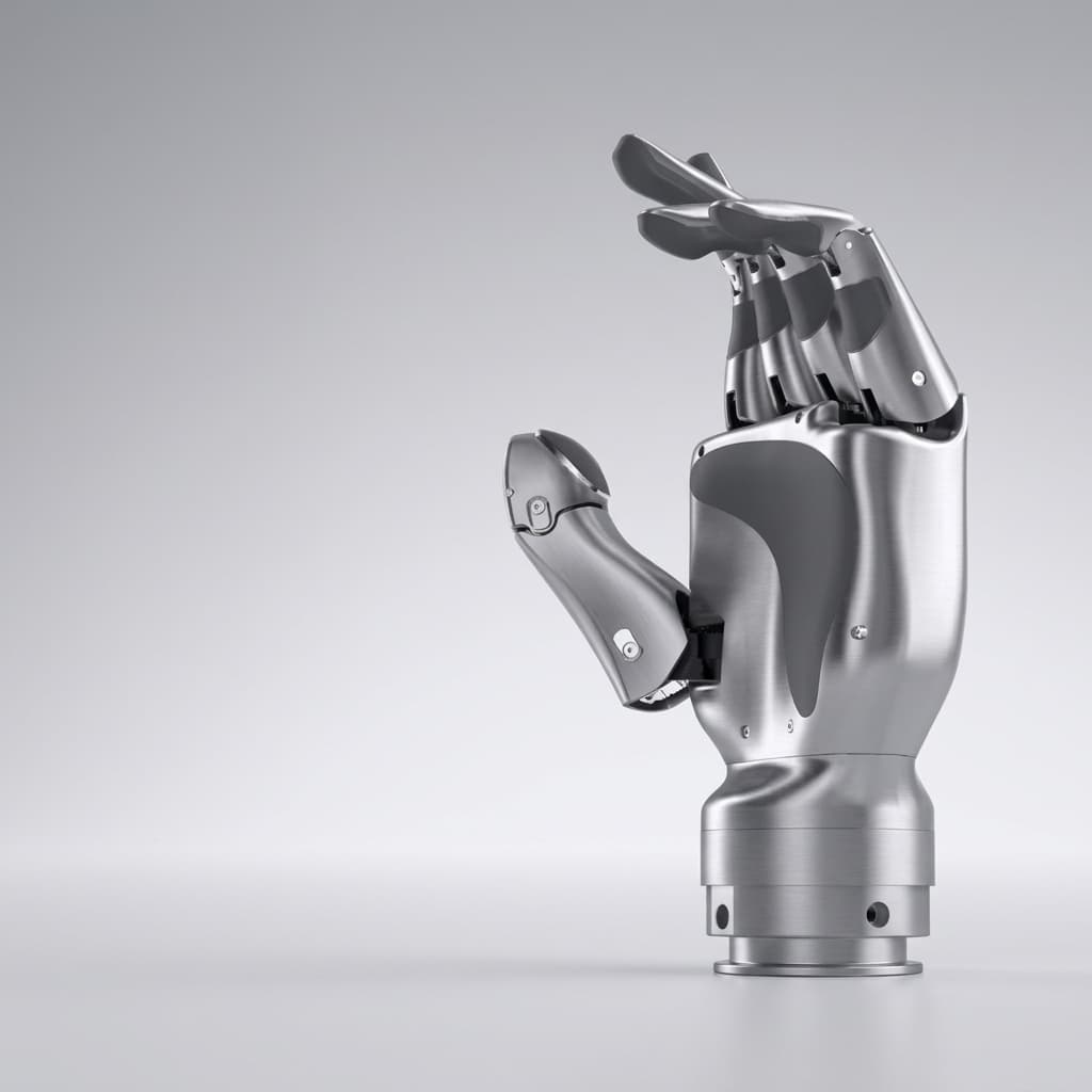
humanoid linear actuator integration detail view
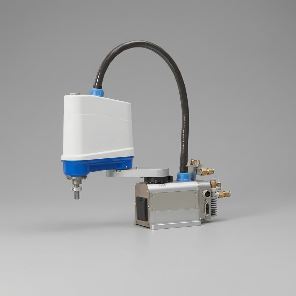
humanoid linear actuator integration application example

Buyer FAQ

Can you support roller screw based humanoid linear actuators?

Yes. Roller screw, ball screw, lead screw, and custom screw-nut assemblies can be reviewed depending on force, stroke, life, and manufacturability.

Is this suitable for humanoid fingers?

It can be. Finger actuators need very tight packaging and clear force-life targets, so early CAD and load-case review is important.

Related Resources

  • Nonstandard Robot Envelopes
  • Dexterous Hand Micro Actuators
  • Quality and Engineering Validation
  • Contact / RFQ

Inquiry Email

[email protected]

Email app

Include target torque/speed, quantity, and delivery location.

Application Engineer

+8618857971991

Talk on WhatsApp

Talk directly about drawings, torque-speed targets, and RFQ data gaps.