
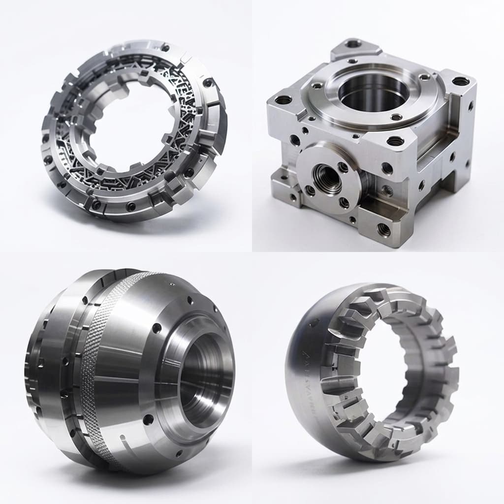
How to Source Custom CNC Housings for Humanoid Actuators
An engineering breakdown of tolerances, material selection, GD&T, and machining costs when moving from benchtop prototype actuators to pilot-production precision CNC housings.
When a humanoid robotics team transitions from off-the-shelf development kits to custom humanoid actuator modules, the complexity of the mechanical housing increases exponentially. A custom actuator housing is not just a protective shell; it is a critical structural element that dictates bearing alignment, gear mesh, heat dissipation, and the overall stiffness of the robot.
Executive Summary (TL;DR)
- Material Selection: 6061-T6 Aluminum is standard, but highly stressed hip/knee joints may require 7075-T6 (Yield Strength: ~503 MPa).
- Precision Tolerances: Strain wave gears require IT6/IT7 tolerance grades (e.g., H7/h6) and concentricity within 0.01-0.02 mm to prevent binding.
- Thermal CTE Mismatch: Aluminum expands twice as fast (23 µm/m·°C) as steel bearings, requiring locknuts or retaining compounds (Loctite 680) to prevent failure at 80°C.
Below, we break down the primary factors that dictate the success (and cost) of sourcing custom actuator housings and interfaces for humanoid robots.
Material Selection for Actuator Housings
Weight is the enemy of a bipedal robot. Almost all high-performance actuator housings are machined from aerospace-grade aluminum alloys, but the specific grade drastically impacts both structural integrity and machining cost.
| Material | Yield Strength (MPa) | Machinability | Best Use Case in Humanoid Robots |
|---|---|---|---|
| Aluminum 6061-T6 | ~276 | Excellent | Standard joint housings, covers, low-stress flanges. Takes anodizing beautifully. |
| Aluminum 7075-T6 | ~503 | Good | Highly stressed joints (hip, knee). Nearly twice as strong as 6061, rivaling mild steel, but prone to stress relief warping during heavy machining. |
| Titanium (Ti-6Al-4V) | ~880 | Poor | Cross-roller bearing retention rings, ultra-stiff output flanges. Used sparingly due to extreme machining cost and weight (denser than Al). |
When specifying materials for pilot builds, do not default to 7075-T6 unless the FEA simulation mandates it. 7075-T6 increases tool wear and cycle time, and its hard-anodizing finish is often matte and less cosmetically appealing than 6061.
Precision Tolerances, GD&T, and Bearing Seats
The most challenging features of any actuator housing are the bearing seats and the mounting interfaces for harmonic or cycloidal reducers.
A high-ratio strain wave gear (harmonic drive) relies entirely on the precision of its input and output bearing support. If the housing bearing seat is out of round or off-center by even a few microns, the wave generator will bind. This causes a massive spike in friction, audible grinding noise, and premature wear.
Critical Tolerances for Pilot Production
For pilot production, your ODM manufacturing partner must employ rigid 5-axis CNC machining and stringent CMM (Coordinate Measuring Machine) inspection and metrology to ensure geometric dimensioning and tolerancing (GD&T) specifications are met:
- Bearing Seat Fits: Typical bearing seats require an IT6 or IT7 tolerance grade (e.g., H7/h6 fits). For a 50mm bearing, this means holding a diameter within exactly 0.016 mm.
- Concentricity & Perpendicularity: The stator bore, rotor bearing seat, and reducer mounting flange must be concentric within 0.01 mm to 0.02 mm.
- Surface Finish: Bearing seats require a surface finish of Ra 0.8 or better to prevent fretting and ensure smooth installation.
Note on Anodizing: Standard Type II anodizing adds ~0.01 mm of thickness, and Type III Hardcoat adds up to 0.05 mm. You must explicitly tell your machine shop whether your CAD dimensions apply Before or After coating, or your bearing seats will be entirely out of spec.
Actuator Housing Defect Matrix & Inspection Checklist
When auditing a new machine shop or inspecting incoming pilot samples, use this defect matrix to catch failure modes before they destroy your motors and reducers:
| Defect Mode | Typical Cause | Consequence in Actuator | ODM Inspection Method |
|---|---|---|---|
| Out-of-Round Bearing Seat | Soft jaws warping the part during clamping; heavy roughing cuts without stress relief. | Harmonic drive binding, audible clicking, sudden current spikes during rotation. | 3-point CMM probing across bearing bore ID; Dial indicator runout test. |
| Non-Concentric Stator Bore | Machining the bearing seat and stator bore in two different setups (flipping the part). | Asymmetrical air gap, rotor scraping against stator (catastrophic failure), cogging torque. | CMM cylindricity and concentricity callout validation. |
| Thin-Wall Chatter | Designing walls <1.5mm thick combined with aggressive endmill feeds. | Cosmetic defects, micro-cracks, and inability to hold an O-ring seal (IP65 failure). | Surface roughness tester (Profilometer); visual inspection. |
| Anodize Buildup in Threads | Failing to plug tapped holes before the anodizing bath. | Screws bind or snap off during assembly. | Go/No-Go thread gauges. |
Thermal Expansion Mismatches
As discussed in our thermal derating guide, the CNC housing acts as the primary heat sink for the frameless stator.
However, engineering teams often overlook the Coefficient of Thermal Expansion (CTE). Aluminum expands at ~23 µm/m·°C, while steel (used in bearings and harmonic drives) expands at only ~12 µm/m·°C. If an aluminum housing gets hot (e.g., 80°C under heavy load), the aluminum bearing seat expands much faster than the steel bearing outer ring. A press-fit bearing can suddenly become a slip-fit, causing the rotor to wobble and strike the stator (a catastrophic failure).
Advanced housing designs mitigate this by using steel sleeve inserts, retaining compounds (like Loctite 680), or specialized bearing retention locknuts rather than relying purely on thermal press-fits.
Controlling Costs in Pilot Production
Prototype machining is inherently expensive, often reaching hundreds of dollars per part. However, as your program moves toward pilot-to-mass production actuators, costs can be reduced by 60-80% by optimizing the design for manufacturability (DFM):
- Minimize Setups (3-Axis vs. 5-Axis): Every time a machinist removes a part from a vise to flip it, tolerance stack-up increases and labor costs double. Design the housing so that the majority of critical features (bearing seats, stator bore, reducer mount) can be machined from one direction in a single setup.
- Standardize Fasteners: Avoid mixing M2, M2.5, and M3 screws of varying lengths. Standardize on one or two fasteners to speed up assembly.
- Avoid Deep, Thin-Walled Pockets: While thin walls (e.g., 1.5mm) reduce weight, they vibrate and chatter violently against the endmill during CNC machining. This forces the machinist to run the machine at 10% speed, skyrocketing the cycle time and cost.
Partnering with an experienced drawing-to-production ODM ensures that your initial CAD is rigorously reviewed for these DFM principles before the first chip is cut, accelerating your timeline from prototype to reliable pilot builds.
3-Axis vs. 5-Axis Machining Strategy
The choice between 3-axis and 5-axis CNC directly impacts part accuracy, lead time, and unit cost. Many teams default to 5-axis because it sounds more capable, but in practice a well-fixtured 3-axis setup can produce better results for simple geometries because the part never needs to be re-clamped.
| Factor | 3-Axis CNC | 5-Axis CNC |
|---|---|---|
| Best for | Flat housings, simple flanges, covers with no undercuts | Complex bearing pockets, angled cable exits, compound datum surfaces |
| Setup count | 2-4 setups per part (flip and re-fixture) | 1-2 setups (tilt and rotate in-place) |
| Tolerance risk | Each re-fixture adds ~0.02 mm datum shift | Single-setup keeps all critical features concentric |
| Machine hourly rate | $40-80/hr (China pilot shops) | $80-160/hr (China pilot shops) |
| Typical cycle time | Longer due to multiple setups, but lower hourly cost | Shorter total cycle, but higher hourly rate |
| When to choose | Prototype housings where cost matters more than complexity | Pilot and production housings where concentricity, cable-through paths, or undercuts demand single-setup accuracy |
Decision rule: If your housing has more than two datum planes that must be concentric (e.g., stator bore + bearing seat + output flange), use 5-axis. If the housing is a simple two-piece clam-shell with parallel faces, 3-axis is cheaper and often more accurate because the fixturing is simpler.
For programs requiring both prototype speed and pilot precision, consider machining the first samples on 3-axis with relaxed tolerances for functional testing, then switching to 5-axis with hardened fixtures once the drawing is frozen. This avoids paying 5-axis rates during the revision-heavy prototype phase.
Surface Treatment and Coating Comparison
Surface treatment is often an afterthought, but it directly affects corrosion resistance, bearing-seat interference, wear life, cosmetic appearance, and thermal emissivity. Choosing the wrong coating can destroy carefully held CNC tolerances.
| Treatment | Typical Thickness | Hardness (HV) | Dimensional Impact | Cost | Best Use in Actuator Housings |
|---|---|---|---|---|---|
| Type II Anodize (clear) | 8-12 µm | 200-400 | +0.005-0.012 mm per side | Low | General housings, covers. Good corrosion resistance. Clean cosmetic finish. |
| Type III Hardcoat Anodize | 25-75 µm | 400-600 | +0.012-0.038 mm per side | Medium | High-wear surfaces, rail slides, output flanges subject to repetitive contact. Must mask bearing seats. |
| Electroless Nickel (EN) | 5-25 µm | 500-700 | +0.005-0.025 mm per side | Medium-High | Excellent uniformity on complex geometry. Superior corrosion resistance. Preferred when anodize color variation is unacceptable. |
| Black Oxide (steel parts) | Under 1 µm | Minimal | Negligible | Low | Steel shafts, bearing retainers, output splines. Virtually zero dimensional change. |
| Passivation (stainless) | 0 (chemical clean) | N/A | None | Low | Stainless steel hollow shafts, fasteners. Removes free iron to prevent rust. |
| Zinc-Nickel Plating | 8-15 µm | 300-400 | +0.008-0.015 mm per side | Medium | Steel inserts, brackets, structural clips. 1000+ hours salt spray resistance. |
Critical warning: Always specify which surfaces must be masked (left uncoated) on your coating drawing. Bearing seats, precision bores, and thread features almost always need masking. If your machine shop sends parts to the anodizer without a masking callout, every bearing press-fit in the batch will be ruined.
For humanoid actuator programs, the most reliable combination is:
- Aluminum housing body: Type II clear anodize with bearing seats masked
- Steel output flange or shaft: Black oxide or electroless nickel
- Aluminum covers and cable routing plates: Type II anodize (color-matched to body)
Supplier Audit Checklist for Actuator Housing Shops
Before committing to a new precision machining supplier for your actuator housing program, verify these eight capabilities on-site or through documented evidence. This checklist separates shops that can hold actuator-grade precision from those that only machine general mechanical parts.
-
CMM capability and calibration certificate: The shop must own or have direct access to a Coordinate Measuring Machine with a current ISO 17025 calibration certificate. Ask to see the last three calibration reports. If they outsource all CMM work to a third party with a two-week turnaround, your pilot build will stall at every inspection gate.
-
Single-setup datum control: Ask the shop to explain how they hold concentricity between the stator bore and bearing seat. If the answer involves flipping the part and using an indicator to re-pick the datum, expect 0.03-0.05 mm runout instead of the 0.01-0.02 mm your reducer needs.
-
Fixture library and soft-jaw practice: A shop that machines actuator housings regularly will have dedicated soft-jaw sets for each housing family. If every job starts with new raw jaws, you are paying setup time on every order and risking fixture-induced distortion.
-
Anodizing process control: Confirm whether the shop anodizes in-house or sends parts out. If outsourced, ask how they communicate masking requirements and how they verify post-anodize dimensions on bearing seats. A missing masking callout on one batch can scrap an entire pilot lot.
-
Material certification and traceability: For aerospace-grade aluminum (6061-T6, 7075-T6), the shop should provide mill certificates (material test reports) with heat lot numbers. This is especially critical if your robot is targeting any certification (CE, UL) that requires material traceability.
-
Packaging and shipping protection: Actuator housings with polished bearing seats are easily damaged by metal-on-metal contact during shipping. Ask to see their packaging method for precision parts. Foam-lined trays, individual VCI bags, and edge protectors are the minimum standard.
-
Revision and ECN handling: When your CAD changes mid-program (and it will), the shop must have a documented process for receiving, acknowledging, and implementing Engineering Change Notices. Shops without ECN discipline will machine parts to the wrong revision and blame unclear communication.
-
Pilot-to-production scalability: If your prototype shop can only run one part at a time on a single machine, your pilot batch of 50 housings will take months. Verify that the shop has multiple machines of the same type, or a clear subcontracting plan for scaling from 5 units to 50+ units without compromising fixture control.
Meeting all eight criteria does not guarantee perfect parts, but failing any single criterion dramatically increases the probability of receiving out-of-spec housings that delay your entire actuator program. Use this checklist alongside the evidence library to build a qualification record for each supplier before issuing a pilot purchase order.
Categories
More Posts
Custom Humanoid Actuator BOM Integration and Sourcing Guide
How funded robotics teams can coordinate motors, reducers, encoders, drivers, bearings, housings, harnesses, validation evidence, and export logistics through one custom actuator ODM workflow.
Custom Humanoid Actuator ODM RFQ Guide
How to prepare a serious custom humanoid actuator RFQ with CAD, torque-speed targets, thermal assumptions, interfaces, and pilot-build expectations.
Frameless vs. Framed Motors in Humanoid Robot Joints: A Packaging and Thermal Analysis
An in-depth engineering analysis on why advanced humanoid robot teams migrate from framed servomotors to frameless torque motors for custom joint actuators to optimize space, weight, and thermal dissipation.