
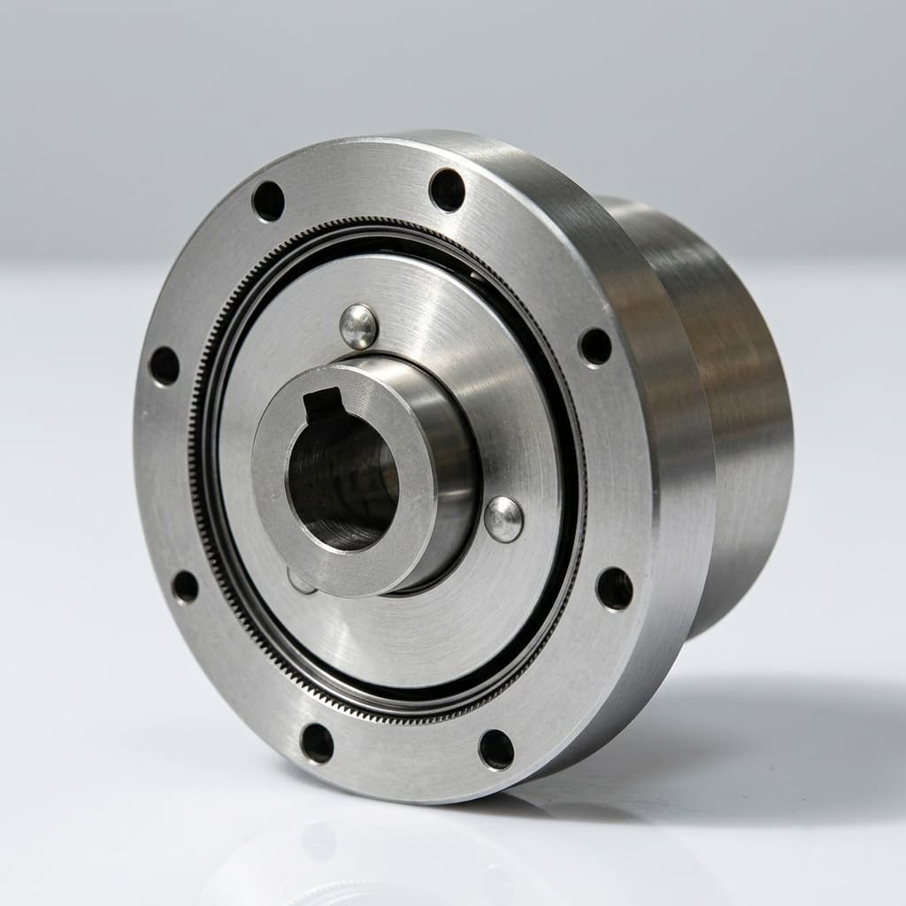
Thermal Derating in Custom Humanoid Actuators
Why peak torque is not enough for humanoid actuator procurement, and how to specify continuous torque, duty cycle, sealed housing conditions, driver heat paths, and validation evidence.
Peak torque is a useful actuator headline, but it is not a procurement specification. In humanoid robots, the same joint may see short acceleration bursts, long holding periods, slow high-current motion, repeated gait cycles, and heat soak inside a sealed body cavity. If the RFQ only asks for peak torque, the supplier can only answer with assumptions.
For custom actuator work, thermal derating is the bridge between an attractive torque number and a joint that survives prototype testing. It defines how much torque is available after heat builds in the motor, reducer, driver, housing, cable path, and robot frame. It also defines what evidence the supplier should deliver before the buyer approves pilot production.
If your team is still choosing the actuator family, start from custom QDD humanoid actuators, frameless hollow-shaft humanoid actuators, or the broader custom humanoid actuator modules page. Use this guide as the thermal decision layer before an FEA and thermal engineering review.
Scope note (published July 24, 2026): This guide is a buyer-side specification framework for custom humanoid actuator RFQs. It does not replace supplier thermal testing, motor characterization, driver validation, or final robot-level qualification.
1. Peak Torque Is Provisional Until Duty Cycle Is Defined
Peak torque answers one narrow question: how much torque can the actuator produce for a short event under defined current, voltage, temperature, and mechanical conditions. The missing part is how long the actuator can do it, how quickly it recovers, and what happens after the joint is already warm.
Humanoid procurement teams should separate three torque numbers:
| Torque field | What it means | Buyer risk if missing |
|---|---|---|
| Peak torque | Short-duration output before current, voltage, mechanical, or temperature limits are reached | The actuator may look strong in a quote but fail during repeated acceleration, fall recovery, or load testing |
| Continuous torque | Output torque that can be sustained under a defined thermal boundary | The joint may overheat while standing, crouching, walking slowly, or holding an arm position |
| Duty-cycle torque | Torque profile across a real movement sequence, including rest and recovery time | The sample may pass a bench burst test but fail after heat soak in the robot body |
In an RFQ, "continuous torque" is incomplete unless the supplier also knows the target speed, ambient temperature, housing condition, cooling path, bus voltage, current limit, and allowable winding or housing temperature. A knee actuator working inside a compact leg shell is not thermally equivalent to the same motor tested on an open bench with a metal fixture and a cooling fan.
2. RFQ Fields That Prevent Thermal Surprises
The most effective thermal discussion starts before the first quote. Add these fields to the RFQ package so the supplier can size the motor, reducer, driver, and housing as a system.
| RFQ field | What to ask | Why it prevents failure |
|---|---|---|
| Continuous torque at speed | State the required torque and RPM for the sustained portion of the motion | Motor heating changes with current, speed, winding resistance, and efficiency |
| Peak torque duration | Define how many milliseconds or seconds the overload must last | A one-second peak and a ten-second peak are different designs |
| Recovery time | State rest time between overload events | Thermal accumulation depends on repeated cycles, not one isolated burst |
| Ambient temperature | Define lab, factory, field, and enclosed-body assumptions | A warm sealed torso or leg cavity reduces usable torque margin |
| Housing boundary | State whether the actuator is open-air, sealed, bolted to a frame, or potted | The housing and robot structure are part of the cooling system |
| Driver location | Define integrated driver, stacked driver, or external driver | Driver losses can heat the motor cavity or create a separate thermal bottleneck |
| Allowable surface temperature | State the maximum external temperature for operator safety and nearby components | Housing limits may derate the actuator before windings reach their limit |
| Evidence format | Request thermal-rise curve, sensor locations, current log, voltage log, and pass/fail criteria | Without evidence format, test reports become hard to compare across suppliers |
For a first-pass package, combine these fields with the minimum data set in the custom humanoid actuator ODM RFQ guide. The goal is not to over-specify every design detail. The goal is to remove the assumptions that create false price comparisons.
3. Use a Derating Margin Before Pilot Builds
A practical starting guardrail is to keep expected sustained operating torque at about 75 percent or less of the supplier's stated continuous torque rating until your team has verified the thermal behavior in the actual robot boundary. This is not a universal law. It is a procurement discipline that prevents a prototype from depending on a perfect lab condition.
Use a larger margin when the actuator has any of these constraints:
- Sealed housing with limited airflow.
- High holding duty, such as a crouched knee or static arm pose.
- Slow speed with high current, where motor heating is high and cooling from motion is limited.
- Integrated driver located inside the actuator cavity.
- Thin hollow-shaft structure with less thermal mass than a solid-core package.
- Nearby battery, PCBA, harness, or sensor components that also have temperature limits.
- Hot ambient environment or outdoor testing.
If the supplier claims a continuous rating, ask for the test boundary behind that number. A useful answer includes ambient temperature, mounting fixture, airflow condition, sensor location, test duration, bus voltage, current limit, motor winding temperature, housing temperature, and whether the reducer and driver were included in the same test.
4. Housing and Robot Frame Are Part of the Heat Path
In custom humanoid actuators, the mechanical package is not only a structural shell. It is also the heat exchanger.
A QDD module may use a large-diameter frameless torque motor to reduce ratio and improve backdrivability. That motor can demand high phase current in a compact space. A hollow-shaft actuator may simplify cable routing through the joint, but the cable path, bearing seats, and reduced material around the shaft can change how heat moves out of the stator and driver area. A reducer-heavy lower-body joint may survive shock load mechanically while still overheating during repeated gait cycles.
Review these housing details before freezing drawings:
- Stator-to-housing contact area and tolerance stack.
- Bearing seat geometry and preload impact on friction.
- Output flange contact to the robot frame.
- Cable exit, hollow-shaft routing, and bend radius near hot surfaces.
- Thermal pad, grease, or bonding layer assumptions where applicable.
- Surface finish, coating, and whether coating reduces contact conductivity.
- Service access for temperature sensor placement during validation.
The best supplier conversation is not "Can you make this smaller?" It is "Which surfaces can carry heat, which surfaces must remain isolated, and what robot-frame boundary should we use for the thermal test?"
5. Driver Heat Path: 48 V and GaN Still Need Evidence
Many humanoid actuator programs use 48 V architecture, compact high-current drivers, and increasingly efficient power devices. Better devices help, but they do not remove the need for thermal evidence. Switching losses, conduction losses, copper thickness, thermal vias, package attach quality, current-sense calibration, connector heating, and firmware current limits all influence the usable actuator envelope.
If the driver is integrated inside the actuator, ask for PCBA validation evidence as part of the actuator evidence pack:
- Driver current limit and peak-current duration.
- MOSFET or GaN device temperature measurement method.
- Copper thickness, thermal-via strategy, and heat-spreader contact assumptions.
- Solder inspection requirement for high-power packages, including X-ray where package type requires it.
- SPI, AOI, ICT, or functional test scope used before final actuator assembly.
- Firmware version, calibration record, and current-sense verification method.
- Thermal interaction between driver board, encoder, brake, and motor cavity.
This is where the quality and engineering validation page becomes more than a QA page. It defines what proof should exist before a sample is treated as representative of pilot production.
6. Thermal Validation Plan by Build Gate
Thermal behavior should be validated in stages. A prototype build does not need the same evidence depth as a production run, but each gate should reduce a known uncertainty.
| Build gate | Thermal question | Evidence to request |
|---|---|---|
| EVT prototype | Can the actuator produce the required torque-speed behavior without immediate thermal failure? | Initial torque-speed curve, thermal-rise test, sensor locations, current and voltage log, basic inspection notes |
| DVT engineering build | Does the actuator survive the target duty cycle in the intended housing boundary? | Repeated load-cycle test, ambient condition, housing temperature map, driver temperature log, post-test backlash or noise check |
| Pilot build | Is the process repeatable across a small batch? | Serial-level test records, burn-in data, torque consistency, resistance or calibration data, nonconformance log |
| Production release | Can the supplier control drift and prove traceability? | End-of-line limits, sampling plan, Cpk target for CTQ dimensions, material traceability, change-control rules, 8D response process |
For lower-body joints, add shock or fall-event assumptions to the same gate plan. For arm and wrist joints, add low-speed smoothness, acoustic behavior, cable fatigue, and holding-temperature checks. For dexterous hand actuators, focus on local heat near tendons, skin material, compact PCBA, and repeated grasp cycles.
7. Thermal RFQ Checklist
Before requesting a formal quote, include these fields in the technical package:
- Joint location and function, such as knee, ankle, hip, shoulder, elbow, wrist, neck, or finger.
- Mechanical envelope, output interface, bearing load, and cable path.
- Peak torque, continuous torque, target speed, overload duration, and recovery time.
- Duty-cycle waveform or representative motion sequence.
- Ambient temperature, sealed or ventilated housing condition, and robot-frame mounting boundary.
- Bus voltage, phase current, driver location, protocol, firmware boundary, and current limit.
- Encoder, brake, temperature sensor, and harness requirements.
- Allowable winding temperature, housing temperature, and nearby component temperature limits.
- Prototype quantity, pilot forecast, annual planning range, destination country, and target schedule.
- Required evidence package: thermal-rise report, torque-speed curve, FAI, CMM, PCBA inspection, burn-in, serial traceability, and 8D response expectation.
If the RFQ does not contain these items, expect the first quote to include hidden assumptions. A good supplier can still start from incomplete data, but the answer should be marked as provisional until the thermal boundary is clear.
8. FAQ: Thermal Derating for Custom Humanoid Actuators
Q: Can we quote from peak torque only? Only for a provisional discussion. A serious quote needs continuous torque, duty cycle, ambient temperature, housing boundary, speed, current limit, and validation expectations.
Q: Is a QDD actuator always hotter than a high-ratio geared actuator? No. QDD designs often use high current and compact packaging, but the final result depends on motor constant, current limit, reduction ratio, efficiency, housing design, driver losses, and duty cycle.
Q: Does a hollow shaft hurt thermal performance? Not automatically. Hollow-shaft packaging changes material distribution, cable routing, bearing layout, and heat path. It should be reviewed as part of the full actuator housing design, not treated as an isolated feature.
Q: What thermal evidence should a sample include? Request a thermal-rise curve, torque-speed data, ambient condition, mounting boundary, sensor locations, current and voltage logs, driver temperature data, and pass/fail criteria.
9. Moving from RFQ to Engineering Review
Thermal derating is not paperwork. It decides whether a humanoid joint can stand, walk, lift, recover, and repeat the same motion after heat soak. The earlier the RFQ defines the thermal boundary, the faster the supplier can separate feasible geometry from attractive but fragile packaging.
If you are preparing a custom humanoid actuator RFQ, send the joint map, CAD envelope, torque-speed target, duty cycle, thermal boundary, voltage, driver location, and evidence requirements through the contact page. We can review whether the next step should be QDD architecture, hollow-shaft integration, reducer selection, FEA, or a controlled prototype build.
Categories
More Posts
Frameless vs. Framed Motors in Humanoid Robot Joints: A Packaging and Thermal Analysis
An in-depth engineering analysis on why advanced humanoid robot teams migrate from framed servomotors to frameless torque motors for custom joint actuators to optimize space, weight, and thermal dissipation.
Harmonic vs. Cycloidal Drives in Custom Humanoid Actuators
Compare harmonic and cycloidal drives for humanoid robot joints. Learn how shock tolerance, backlash, and weight impact procurement and engineering decisions.
Custom Humanoid Actuator ODM RFQ Guide
How to prepare a serious custom humanoid actuator RFQ with CAD, torque-speed targets, thermal assumptions, interfaces, and pilot-build expectations.