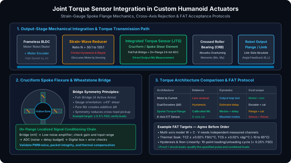
Joint Torque Sensors in Custom Humanoid Actuators: Strain-Gauge Flanges, Cross-Axis Moment Rejection, Force Control Bandwidth, and Sourcing Acceptance Protocols
Compare joint torque sensors for humanoid actuators: spoke strain-gauge flanges, cross-axis rejection, force bandwidth, and FAT calibration. Request an RFQ.
Joint torque sensors (JTS) measure transmitted torque at an instrumented joint output, after the speed reducer. Shortlist a strain-gauge flange when friction and transmission uncertainty exceed your contact-control error budget. Compare it with calibrated motor-current estimation and dual-encoder deflection sensing using the same load, temperature, accuracy, and latency requirements. Gear ratio alone does not determine the correct architecture. The sensor measures torque through its own load path; external contact torque still requires compensation for link inertia, gravity, and downstream friction. Its presence alone does not establish safe physical human-robot interaction.
Published and reviewed: 13 November 2026. This global engineering and procurement guide serves robotics hardware architects, mechatronics leads, control system engineers, and ODM sourcing teams procuring custom humanoid actuators. Scope: rotary joint modules featuring integrated hollow-shaft torque sensing flanges. Linear actuators, multi-axis end-effector load cells, and non-contact magnetoelastic arrays require distinct mechanical models. Numerical examples and Factory Acceptance Test (FAT) thresholds below represent hypothetical engineering proposals, not measured product results or unilateral certified joint ratings.
Executive Sourcing & Architecture Summary
- Direct vs. indirect measurement: A flange can measure transmitted torque downstream of reducer losses. Current-based and dual-encoder estimates remain candidates when their calibrated residual errors satisfy the task.
- Stiffness vs. sensitivity: Higher torsional stiffness reduces elastic twist but can reduce gauge strain. Specify usable input-referred noise and mounted resonance rather than ADC bit count alone.
- Cross-axis rejection: Bearing load paths, bridge symmetry, and calibration must be evaluated together. A single torque channel cannot independently identify all six applied forces and moments.
- Localize analog electronics: Short, shielded bridge wiring and nearby digitization reduce PWM pickup. Grounding, power integrity, and bus error detection still require installed testing.
- Procurement cost model: Quote the flexure, gauge bonding, electronics, calibration time, NRE, and yield allowance separately. No universal sensor cost premium or force bandwidth applies to every joint.
For a custom engineering assessment of your actuator output stack, share joint torque-speed envelopes, target bandwidth, and mechanical dimensions with our custom humanoid actuator modules engineering desk.
1. The Dynamic Control Dilemma: When Indirect Torque Sensing Is Insufficient
Whole-body control frameworks for humanoid robots—such as Model Predictive Control (MPC), operational space impedance control, and virtual compliance—rely fundamentally on knowing the instantaneous interaction torque (τ_ext) between each joint and the environment.
Robotics architects evaluate three primary topologies for obtaining this feedback:
- Indirect (Motor Phase Current):
Tau_ideal = i_q * K_t * N. This is an ideal torque estimate before correcting transmission losses, inertia, and torque-constant variation. DefineK_tusing the same current convention as the drive. - Semi-Direct (Dual-Encoder Deflection):
Tau_est = K_reducer * (theta_m / N - theta_L)for an agreed positive torque direction. This linear approximation needs an identified stiffness and hysteresis model. - Direct (Joint Torque Sensor Flange):
Tau_measured = a * (V_bridge - V_zero)for a calibrated single-channel model. Gainaincludes excitation and signal-chain scaling; temperature and cross-load corrections may also be needed.
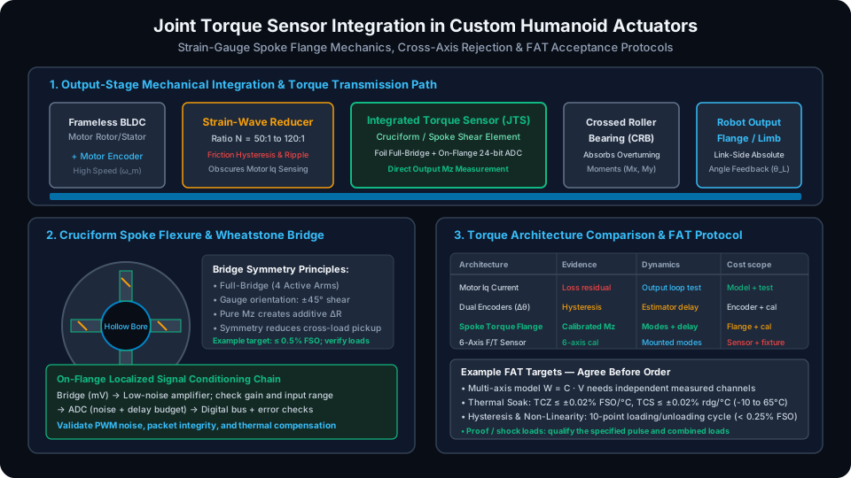
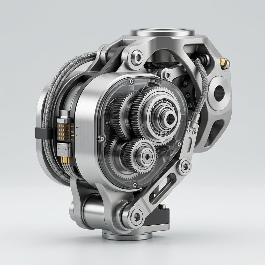
Conceptual architecture illustration; not a tested product drawing or a guarantee of sensor performance.
1.1 The Breakdown of Motor-Current Torque Estimation (i_q * K_t * N)
In direct-drive or low-ratio quasi-direct drive (QDD) actuators with gear ratios N ≤ 10:1, motor phase current measured via Field-Oriented Control (FOC) shunt resistors or Hall-effect sensors correlates reasonably with output torque. However, to achieve compact humanoid packaging in hip pitch, knee flexion, torso yaw, and shoulder joints, designers frequently deploy strain wave (harmonic) or cycloidal speed reducers with ratios between 50:1 and 120:1.
In these high-ratio mechanisms, indirect torque estimation can accumulate error through three physical phenomena:
- Coulomb and Viscous Friction Losses: Speed reducers exhibit substantial breakaway friction and velocity-dependent grease shear resistance. At low speeds and direction reversals, the loss depends on reducer preload, seals, lubricant, load, and temperature; request measured residuals rather than assuming a fixed loss percentage.
- Torque Ripple and Cogging: Strain-wave wave generators and gear teeth meshing produce periodic torque harmonics at multiples of the motor velocity. Current sensing cannot distinguish whether a current spike is accelerating the robot limb or fighting internal gear meshing resistance.
- Temperature-Dependent Viscosity: As an actuator warms, lubricant viscosity and friction change. Repeating a current-versus-output-torque sweep at cold and stabilized operating temperatures reveals the resulting estimator bias; a universal viscosity drop or torque increase cannot be assumed.
Consequently, unmodeled losses can mask low-amplitude contact torque. Qualify the estimator against the minimum contact signal and the permitted error under load reversals before selecting it for interaction tasks.
1.2 The Bottlenecks of Dual-Encoder Deflection Sensing (Tau = K_reducer * Delta_Theta)
As explored in our technical analysis of dual-encoder architectures, link-side absolute encoders measure the actual angular position (theta_L) after the reducer, while the motor-side encoder measures rotor position (theta_m). The angular difference Delta_Theta = (theta_m / N) - theta_L represents the torsional deflection of the drivetrain.
While appealing because it avoids an additional sensor component, using deflection angle to infer torque has severe practical limitations:
- Non-Linear Torsional Stiffness: Strain-wave reducers exhibit soft-spring characteristics near zero torque, transitioning to higher stiffness at rated torque. Identify the torque-versus-angle curve over the working range; a piecewise fit or hysteresis model may be appropriate.
- Hysteresis and Lost Motion: Mechanical lost motion and material hysteresis make torque depend on loading history. Require bidirectional torque-versus-deflection curves; do not infer a universal deadband from the reducer type.
- Noise and Estimator Delay: Static elastic torque estimation uses deflection directly and does not require differentiation. Velocity-dependent damping terms may require derivatives or an observer. Encoder quantization, synchronization, and chosen filters determine noise and delay; neither a fixed delay nor a universal force bandwidth follows from using dual encoders.
Select a dedicated flange when the installed indirect estimator cannot meet the required error and dynamic response. Validate the complete closed loop with the intended limb inertia: a fast torque sensor cannot remove a structural resonance or certify contact safety.
2. Mechanical Spring Element Geometries: Spoke / Cruciform Shear Beams vs. Diaphragm Flanges
A joint torque sensor is fundamentally an elastic mechanical spring instrumented with strain transducers. Its geometry must maximize strain under pure torsional shear (Mz) while providing maximum structural rigidity against parasitic forces and moments (Fx, Fy, Fz, Mx, My).
2.1 Cruciform / 4-Spoke Radial Shear Beams
One candidate architecture for custom humanoid actuators is a 4-spoke (or 8-spoke) radial cruciform flange machined from high-yield-strength alloy steel (e.g., 40CrNiMoA / AISI 4340 or 17-4PH precipitation-hardened stainless steel) or aircraft-grade 7075-T6 aluminum.
- Kinematic Function: The inner hub bolts directly to the reducer output or central hollow shaft, while the outer ring fastens to the joint output flange and bearing inner race. Torsional moment Mz forces the spokes into pure bending or shear deformation.
- Symmetry and Load Cancellation: Opposing spokes experience equal and opposite bending under non-torsional moments. Under an overturning moment Mx, the top and bottom spokes experience tension and compression, while the side spokes experience twist. When wired into a symmetrical full Wheatstone bridge, the bridge can reduce these parasitic contributions to first order; mounting asymmetry and gauge mismatch leave residual error.
- Packaging: The spoke design naturally accommodates a large central hollow bore (12 mm to 30 mm), allowing high-voltage DC bus cables, motor phase wires, and communication lines to pass unimpeded through the joint center.
2.2 Annular Diaphragm & Thin-Wall Torsion Tubes
In compact joints where axial length is extremely restricted (e.g., wrist roll or elbow pitch), engineers frequently consider thin-wall annular diaphragms or torsion tubes:
- Mechanics: For a closed, thin-wall circular torsion tube under elastic pure torsion, average wall shear stress is
tau = Mz / (2 * pi * r^2 * t), whereris mean radius andtis wall thickness. This tube relation is not a general annular-diaphragm sizing equation. - Trade-offs: While offering high torsional stiffness per unit length, thin diaphragms can be sensitive to axial thrust and bending, depending on web geometry and boundary conditions. Evaluate buckling, stress, and cross-load sensitivity using the actual support arrangement; bearing isolation may be necessary.
2.3 The Core Design Equation: Torsional Stiffness (Kt) vs. Micro-Strain
The fundamental engineering trade-off in joint torque sensor design is governed by the structural relationship between mechanical deflection, resonant frequency, and electrical signal amplitude:
Kt = Delta_Mz / Delta_theta_s
This is local torsional stiffness in Nm/rad over a stated load interval. For a uniform shaft in pure torsion, Kt = G * J_t / L; a radial spoke flange generally requires a beam model or finite-element analysis rather than substituting spoke length into that shaft equation. Validate the model against measured torque-versus-angle curves.
For a gauge in uniaxial elastic strain, epsilon = sigma / E. In pure shear, gamma = tau / G, and gauges at ±45° to the shear axes see principal strains of approximately +gamma/2 and -gamma/2. Gauge placement and local stress state determine the bridge signal. These relations describe small elastic deformation, not fatigue life or allowable overload.
Reproducible signal example: assume four equally active gauges, two in tension and two in compression, with strain magnitude 200 με, gauge factor GF = 2, and excitation V_exc = 3.3 V. For a balanced additive full bridge at small strain:
V_out / V_exc approx GF * epsilon = 0.0004 = 0.4 mV/V
V_out approx 3.3 * 0.0004 = 1.32 mV
Resolving 0.1% of that full-scale signal requires about 1.32 μV input-referred resolution over the stated measurement bandwidth, before allocating drift and other errors. A half bridge or quarter bridge has a different sensitivity. Increasing strain raises signal amplitude, while the resulting stiffness, yield margin, and fatigue behavior need a separate mechanical check. This arithmetic is hypothetical and is not a measured sensor result.
3. Transducer Technologies: Metal Foil vs. Semiconductor vs. Magnetoelastic Sensing
Choosing the physical strain-sensing element dictates sensor thermal stability, signal-to-noise ratio, shock tolerance, and volume production costs.
| Sensing Technology | Signal Principle | Thermal Qualification | Mechanical Qualification | Electrical Qualification | ODM Sourcing Decision |
|---|---|---|---|---|---|
| Bonded Metal Foil Gauges | Resistance changes with strain; gauge factor near 2 is a common starting assumption | Verify gauge alloy, substrate matching, adhesive creep, and compensated zero/span | Test flexure fatigue, bond integrity, and assembled overload response | Budget bridge excitation, input noise, and lead resistance | Shortlist when bonding control and serialized calibration are available |
| Semiconductor Piezoresistive Gauges | Higher strain sensitivity; coefficients depend on material and fabrication | Require compensated data over the installed temperature range | Verify package and bond survival under the specified shock pulse | Check gain, nonlinearity, self-heating, and drift | Higher signal does not automatically prove better system accuracy |
| Deposited Thin-Film Elements | Resistive film integrated with an insulating layer on the flexure | Ask for thermal cycling and long-term stability evidence | Verify film adhesion and flexure processing consistency | Request measured sensitivity and noise at the intended bandwidth | Compare process capability, tooling cost, and production yield |
| Non-Contact Magnetoelastic Sensing | Stress changes magnetic properties | Characterize temperature and magnetic-history effects | Evaluate shaft material, geometry, and remanence | Test immunity to the actual motor fringe fields and current spectrum | Consider as a separate architecture; do not transfer strain-gauge calibration assumptions |
No sensing technology has a universal shock rating, thermal coefficient, or accuracy. Require assembled-device evidence under the same test conditions before ranking supplier offers.
4. Cross-Axis Decoupling: Isolating Torsion from Overturning Moments and Axial Thrust
A humanoid actuator output flange is constantly subjected to 6-degree-of-freedom wrench vectors:
W = [Fx, Fy, Fz, Mx, My, Mz]^T
In a knee joint during stance phase, the knee actuator delivers torsional drive torque (Mz), but simultaneous ground reaction forces exert massive lateral bending moments (Mx, joint valgus/varus), frontal bending moments (My), and axial compression (Fz).
4.1 Mechanical Parasitic Rejection
To ensure that Mx, My, Fz do not register as false joint torque:
- Bearing Isolation: Support the joint output flange with an appropriately sized bearing arrangement, such as a crossed roller bearing (CRB). The bearing and housing should route non-torsional loads around the measuring flexure where possible. The isolated fraction depends on the actual mechanical load path and must be measured; bearing type alone cannot establish it.
- Shear-Mode Gauge Orientation: Foil gauges are placed on the neutral bending axis of each spoke at ±45° angles relative to the spoke centerline. Under pure torsion, the principal stresses are tension (+45°) and compression (-45°). A balanced bridge can reject common strain components to first order. Actual spoke stress fields and assembly tolerances prevent assuming complete cancellation of axial or bending loads.
4.2 Multi-Axis Calibration & Decoupling Matrix (W = C * V)
Even with optimal mechanical symmetry, manufacturing tolerances, machining runout, and gauge alignment errors produce residual cross-axis sensitivity that must be characterized under specified forces and moments.
In high-performance actuators, the torque sensor is factory-calibrated on a multi-axis dynamometer rig to establish a decoupling matrix:
[Mx, My, Mz]^T = C * [V_ch1, V_ch2, V_ch3]^T
Here V_ch must be three independent measured channels with sufficient sensitivity to the three moments. Determine C from traceable loads and verify residuals with separate validation load cases. A 6-axis model requires enough independent channels for all six components and a well-conditioned calibration matrix. A single torque bridge cannot computationally separate arbitrary unmeasured cross-loads. An illustrative residual target is ≤ 0.5% FSO, verified at named axial and bending loads rather than promised by the matrix alone. The ATI six-axis system overview distinguishes full wrench sensing from a single-axis torque measurement.
5. Signal Conditioning & Electrical Integration: Reducing PWM Drive EMI
The electrical environment inside a custom humanoid actuator is extremely harsh. For an illustrative 48V/60V joint with PWM in the tens of kilohertz, switching edges can couple noise into low-level bridge signals. Actual edge rate, inverter technology, layout, and cable geometry determine the interference spectrum.
Routing low-level analog strain-gauge signals (microvolts) across flex cables past the motor stator to an external controller increases exposure to PWM pickup; quantify the installed noise rather than assuming either inevitable failure or complete immunity.
[Strain Gauge Wheatstone Bridge (specified mV/V sensitivity)]
                      │ (Short differential traces, controlled return path)
                      ▼
[Ultra-Low Noise Instrumentation Amp / PGA (Gain selected from signal and headroom budget)]
                      │
                      ▼
[ADC (rate, noise, settling, and group delay specified together)]
                      │
                      ▼
[Digital Filter & Calibration Matrix (Onboard DSP / Real-Time MCU)]
                      │
                      ▼ (High-speed digital bus: EtherCAT / SPI / BiSS-C)
[Actuator Main Servo Inverter / Whole-Body Controller]
5.1 On-Flange Localized Analog Front End (AFE)
Nearby digitization is one useful integration choice. Compare it with a shielded remote AFE when heat, access, or packaging favors that arrangement:
- Integrated Rigid-Flex PCB: An annular PCB near the flexure can shorten analog leads. Specify mounting, strain relief, thermal exposure, and serviceability; the PCB need not always rotate with the output.
- Precision Low-Drift Instrumentation Amplifier: Evaluate input-referred noise, overload recovery, common-mode range, and frequency-dependent CMRR. A DC CMRR value alone does not predict rejection of PWM edges.
- 24-bit Delta-Sigma ADC: The TI ADS131M04 is one 24-bit simultaneous-sampling ADC candidate with a programmable PGA and SPI. Select gain and data rate from its noise and filter specifications. Nominal 24-bit output does not establish 24-bit usable resolution, installed accuracy, or acceptable group delay.
- Digital Transmission: SPI can connect the ADC locally; an appropriate transceiver or controller provides RS-485 or EtherCAT where required. Digital links can still suffer common-mode disturbances, packet errors, and timing jitter. Specify CRC, error handling, and any required galvanic isolation explicitly.
5.2 Thermal Drift Compensation (TCZ and TCS)
Motor heat and local self-heating can create temperature gradients across the flange. Specify the sensor operating range from the installed thermal model and measured duty cycle, including cold start and warm steady state.
Thermal drift degrades torque accuracy through two distinct mechanisms:
- Temperature Coefficient of Zero (TCZ): Asymmetrical thermal expansion or unequal gauge resistance shifts the zero-torque bridge balance. Example target specification: ≤ ±0.02% FSO/°C.
- Temperature Coefficient of Span (TCS): Changes in elastic modulus, gauge factor, excitation, and amplifier gain change sensitivity. Coefficients depend on material and the assembled signal chain. Example target specification: ≤ ±0.02% rdg/°C.
Mitigation: The on-flange PCB incorporates a temperature measurement near the bridge (for example, a PT1000 with an appropriate readout circuit or a digital temperature sensor) located adjacent to the strain bridge. The local MCU executes real-time polynomial compensation:
Tau_compensated = (Tau_raw - Zero(T)) * Span(T)
Fit Zero(T) and the multiplicative scale correction Span(T) to chamber calibration data, then validate intermediate temperatures and thermal transients independently. A polynomial degree is a model choice. At a proposed zero-drift limit of 0.02% FSO/°C, a 50°C change permits 1% FSO accumulated zero change if the coefficient is treated as a worst-case constant; it does not mean total accuracy is 0.02%.
6. Closed-Loop Force Bandwidth and Mechanical Resonance
A common procurement pitfall is confusing the sensor's raw electrical ADC sampling rate with the closed-loop force control bandwidth.
A sensor may output digital torque packets at 10 kHz, but the usable closed-loop torque control bandwidth is bounded by mechanical resonance and controller filter latency:
For an ideal two-inertia model with one elastic coupling:
omega_n = sqrt(Kt * (1 / (J_m * N^2) + 1 / J_L))
f_n = omega_n / (2 * pi)
J_m * N^2 is motor inertia reflected to the output, J_L is link inertia, and Kt is coupling stiffness. Only when reflected motor inertia is much larger than link inertia does omega_n approx sqrt(Kt / J_L) apply. Reducer, sensor, and link compliance in series lower effective stiffness: 1 / K_eff = 1 / K_sensor + 1 / K_reducer + 1 / K_link. Real multi-body joints have additional modes and damping.
Hypothetical, reproducible screening example: take J_L = 0.08 kg*m^2, effective stiffness Kt = 20,000 Nm/rad, and the large-reflected-inertia approximation:
omega_n = sqrt(20,000 / 0.08) = 500 rad/s
f_n = 500 / (2 * pi) = 79.6 Hz
If a preliminary design allocates closed-loop bandwidth to 0.3 of this resonance, the target is about 24 Hz. A 0.7 fraction would be about 56 Hz, but requires justified damping and measured stability margins. These are screening assumptions, not universal controller filter settings. For a hypothetical 150 Hz target, retaining the same inertia and a 0.3 fraction would require approximately 0.08 * (2 * pi * 150 / 0.3)^2 = 790,000 Nm/rad effective stiffness. Even a 0.7 fraction implies about 145,000 Nm/rad. Increasing sensor stiffness alone cannot achieve that if another series element dominates compliance.
Latency also consumes phase margin. A pure delay t_delay contributes 360 * f * t_delay degrees of phase lag. A 100 μs delay contributes 3.6° at 100 Hz, before filter and plant phase. Define sensor output rate, analog/digital filter delay, transport latency, and measured closed-loop bandwidth separately. Confirm the final response with the installed inertia and control settings.
For a bandwidth review, include your load inertia, stiffness model, and latency budget with the engineering inquiry.
7. Engineering Architecture Comparison: Direct vs. Indirect Torque Feedback
Before committing to custom tooling and NRE for integrated torque sensors, mechatronics teams must evaluate all four torque observation strategies across their robot's complete Degree-of-Freedom (DOF) budget.
The rows below compare architectural trade-offs, not measured product rankings or supplier quotations. Report accuracy against a defined full-scale output (FSO), temperature, mounting condition, and bandwidth.
| Engineering Parameter | 1. Motor Current Estimate | 2. Dual-Encoder Deflection | 3. Integrated Torque Flange | 4. External 6-Axis Load Cell |
|---|---|---|---|---|
| Measurement Location | Motor electrical measurements, before reducer | Relative angle across transmission | Instrumented output torque path | Tool or foot mounting interface |
| Accuracy Evidence | Residual against reference torque after loss compensation | Bidirectional torque-deflection calibration | Serialized installed torque calibration | Calibration for all six channels and specified ranges |
| Reversal Behavior | Friction and current offset influence estimate | Hysteresis and lost motion affect inference | Flexure, adhesive, and mounting hysteresis remain | Channel hysteresis and mounting effects remain |
| Force Bandwidth | Current-loop bandwidth does not establish output force bandwidth | Estimator noise, filtering, and mechanics limit response | Sensor response, delay, and joint modes limit response | Transducer modes and the complete robot loop limit response |
| Cross-Axis Loads | Does not directly measure bending or thrust | Housing deformation can affect angles | Require residual torque under named cross-loads | Six independent channels allow calibrated wrench reconstruction |
| Packaging Evidence | Account for current sensors and electronics already present | Quote encoder readhead, target, mount, and wiring | Quote flexure, PCB, bearing interface, and bore clearance | Quote transducer, adapters, harness, and added distal inertia |
| Cost Comparison | Separate model-identification and validation effort | Include encoder, assembly, and calibration costs | Include gauges, bonding, electronics, calibration, NRE, and yield | Include purchased sensor, interfaces, and integration effort |
| Selection Boundary | Use when calibrated torque errors satisfy the task | Use when the identified deflection model meets the task | Use when direct transmitted-torque measurement justifies integration | Use when the contact task requires a multi-axis wrench |
Request quotations at the same quantity, drawing revision, currency, delivery terms, and calibration scope. Separate one-time engineering charges from recurring unit cost, then compare the cost of maintaining the calibration in service.
8. Factory Acceptance Testing (FAT) & Calibration Sourcing Protocols
When procuring custom humanoid actuators with integrated torque sensors, procurement specifications must mandate serialized calibration certificates. Never accept uncalibrated sensors or generic manufacturer data sheets.
Agree on the following six test categories before releasing production purchase orders. All numerical limits are illustrative negotiating targets, not standards-mandated limits or claims about available products. Define FSO as the positive rated torque magnitude for these examples; state explicitly if a supplier instead uses the full bipolar span. Record fixture stiffness, calibration uncertainty, serial number, firmware version, and the exact simultaneous load case. Distinguish per-unit production checks from design-qualification or potentially damaging tests.
| Inspection Test Protocol | Measured Parameter | Contract Acceptance Threshold | Test Rig & Verification Methodology | Sourcing & Engineering Verdict |
|---|---|---|---|---|
| 1. Static Linearity & Hysteresis | End-point non-linearity, hysteresis error, repeatability | Non-linearity ≤ ±0.25% FSO; Hysteresis ≤ ±0.20% FSO | Traceable reference torque transducer or characterized lever arm and calibrated masses; 10 loading/unloading steps in both directions. Include arm geometry, local gravity, alignment, and measurement uncertainty. | Validates pure elastic spring response and proper gauge bonding without adhesive creep. |
| 2. Cross-Axis Crosstalk Verification | Output torque change (Delta_Mz) under pure bending (Mx, My) and thrust (Fz) | Example: crosstalk ≤ ±0.50% FSO at agreed Mx, My, and Fz limits | Multi-axis static test fixture; apply named bending and axial loads separately and in agreed combinations while holding reference torque; log residual Mz error. | Confirms mechanical spoke symmetry and software decoupling matrix calibration integrity. |
| 3. Thermal Soak Drift (TCZ & TCS) | Zero-point drift (TCZ) and sensitivity span shift (TCS) | TCZ ≤ ±0.02% FSO/°C; TCS ≤ ±0.02% rdg/°C | Environmental chamber soak (-10°C to +65°C, 1°C/min ramp, 2-hour dwell at extremes); measure zero shift and rated torque deflection. | Verifies onboard temperature sensor calibration and automated polynomial thermal compensation. |
| 4. Dynamic Frequency Response | -3 dB closed-loop bandwidth and mechanical resonance peak | Agree on -3 dB bandwidth, phase/gain margins, resonance separation, and total delay for the installed load | Chirp or stepped sweep within qualified load limits, with an independently characterized reference sensor. Record installed inertia, controller gains, filter settings, and all relevant modes. | Checks the specified operating configuration; one frequency sweep does not guarantee stability for every robot pose or contact condition. |
| 5. Shock Overload Margin | Zero shift and calibration retention after transient impact shock | Example: zero shift < 0.1% FSO after a supplier-approved proof load; shock peak, duration, and repetitions agreed separately | Contained qualification fixture with instrumented torque-time pulse, combined-load limits, and post-test recalibration. Do not impose a generic 300% impact on an unqualified assembly. | Evaluates the named proof or impact case; it does not establish robot-fall survival or a safety rating. |
| 6. EMI & Noise Immunity Under PWM Stall | RMS noise floor and peak-to-peak torque ripple under locked rotor | Example: noise ≤ 0.05% FSO RMS in a specified band; agree on peak-error and packet-loss limits | Use a rated reaction fixture, supplier-approved current and duty, cooling, and thermal cutoffs. Log PWM-on/off data, sample rate, filter bandwidth, and packet timestamps; separate real transmitted-torque ripple from electrical pickup. | Validates localized AFE shielding, ground plane isolation, and differential ADC common-mode rejection. |
9. 10-Point Engineering & Procurement Checklist for Torque-Sensing Actuator RFQs
Before submitting an RFQ for custom humanoid actuator modules with integrated torque sensing, ensure your specification package answers every technical requirement below:
- 1. Torque Range & Overload Envelope: Specify continuous operating torque, peak dynamic torque, and a separate structural proof-load and impact envelope. Size against recorded load cases and all limiting components; do not assume a universal robot-fall multiplier.
- 2. Torsional Stiffness Boundary: State the minimum acceptable torsional stiffness (Kt, in Nm/rad or kNm/rad) derived from your robot limb's inertia and resonance frequency budget.
- 3. Cross-Axis Load Spectrum: Define expected simultaneous radial loads (Fr), axial thrust (Fz), and overturning moments (Mx, My), along with the maximum allowable crosstalk percentage (< 0.5% FSO).
- 4. Sensing Element & Adhesive System: Identify the proposed sensing element, bonding or deposition process, installed temperature range, and long-term creep limit. Accept alternatives on matched qualification evidence.
- 5. Signal Chain & ADC Integration: Specify required input-referred noise, full-scale signal, excitation, sample rate, group delay, and mounted EMI performance. Request the gain/filter settings and effective resolution at that operating point.
- 6. Digital Interface & Synchronous Protocol: Specify the implemented interface and data format, synchronization method, timestamp definition, total sensor-to-controller latency, jitter, and error response. Distinguish bus transfer time from ADC/filter delay.
- 7. Thermal Compensation Algorithm: Require integrated onboard temperature sensing adjacent to the strain bridge, with verified polynomial TCZ and TCS correction parameters flashed to on-sensor EEPROM.
- 8. Central Hollow Bore Clearance: Define usable internal bore diameter (e.g., 14 mm to 25 mm) to ensure compatibility with power bus cables, communication harnesses, and bearing retention rings.
- 9. Mechanical Flange Interface: Provide 3D CAD step files detailing bolt circle diameters, dowel pin locating tolerances, pilot boss runout (≤ 0.015 mm), and fastener torque grades.
- 10. Calibration Deliverables & Traceability: Mandate individual serialized calibration certificates for each shipped unit, including 10-point linearity/hysteresis plots, calibration coefficients and any applicable multi-axis matrices, and raw vs. compensated thermal curves.
10. Frequently Asked Questions (FAQ)
When should a humanoid actuator use a joint torque sensor instead of motor-current estimation?
Use a dedicated flange when measured current-based torque errors under reversal, temperature, and load exceed the application budget. Reducer ratio alone is not decisive. Output sensing avoids having to infer transmitted torque from upstream motor current, but external contact torque still requires a dynamics model.
How can a joint torque sensor reject bending moments and axial forces?
Route cross-loads through the bearing and housing where practical, use a bridge matched to the flexure stress field, and validate residual torque error under named cross-loads. A multichannel calibration matrix requires independent channels; one torque bridge cannot separate six unknown loads. A 0.5% FSO residual is an example acceptance target, not a guaranteed result.
What is the trade-off between torque sensor stiffness and signal-to-noise ratio?
Higher stiffness reduces twist but can reduce local gauge strain. With four equally active additive gauges at 200 microstrain, gauge factor 2, and 3.3 V excitation, the small-strain full-bridge example gives 1.32 mV full scale. A 0.1% resolution target therefore corresponds to 1.32 microvolts before other error allocations. Geometry and measured input noise decide feasibility.
Must the analog front end and ADC be mounted on the torque flange?
Nearby digitization can reduce analog lead exposure to motor PWM, but a shielded remote AFE may suit the thermal or service requirements. Neither local digitization nor a digital bus makes the system immune to interference. Qualify noise, packet integrity, and timing with the actual inverter and harness.
How should thermal drift be specified for a joint torque sensor?
Separate zero drift in percent FSO per degree from span drift in percent of reading per degree. Define temperature range, dwell, gradients, warm-up, and residual errors after compensation. An example 0.02% FSO per degree zero-drift limit permits 1% FSO change over 50 degrees under a constant worst-case coefficient; it is not the total accuracy.
Can dual encoders replace a dedicated joint torque sensor in humanoid legs?
They can support torque estimation when identified transmission stiffness, hysteresis, encoder noise, and synchronization errors meet the task requirements. Static deflection-based torque estimation does not require differentiation. Compare installed estimation error and closed-loop frequency response; neither architecture has a universal bandwidth or contact-safety guarantee.
11. Moving from Sizing to Custom ODM Actuator Production
Integrating precision joint torque sensing requires careful co-design of the harmonic/cycloidal reducer, crossed roller bearing, hollow-shaft cable routing, and on-joint digital electronics. Sourcing teams should seek manufacturing partners capable of delivering fully integrated, dynamometer-calibrated actuator modules with serialized calibration data.
If your engineering team is specifying actuators for bipedal legs, torso assemblies, or dexterous manipulators:
- Explore our integrated custom humanoid actuator modules.
- Review high-load packaging for custom humanoid leg actuators.
- Examine hollow-shaft electrical integration in frameless hollow-shaft humanoid actuators.
- Review our design-for-manufacturing capabilities in custom actuator housings and interfaces.
- Submit your joint torque-speed curves, stiffness requirements, dimensional envelopes, and target quantities via our engineering inquiry page, or email your CAD step files directly to [email protected].
12. Sources & Authoritative References
Reference review date: 13 November 2026. These primary sources support measurement principles and the named component features. They do not certify humanoid actuator performance, prices, the illustrative FAT limits, or our simplified control calculations. No first-party hardware measurements are claimed in this article.
- HBK / HBM — Measuring Torque Correctly. Official torque-measurement handbook. Sections 2.4 and 3.1 explain strain-gauge torque measurement and measuring-body designs, including spoke/shear structures; subsequent chapters discuss influence quantities and calibration. This is a large PDF (about 17 MB).
- ATI Industrial Automation — Multi-Axis Force/Torque Sensors. Manufacturer overview of six-component force/torque measurement and its transducer, cable, and acquisition-system boundary. It does not establish a universal crosstalk or bandwidth figure for a single-axis humanoid joint sensor.
- Texas Instruments — ADS131M04 Product Documentation. Official specifications for a simultaneous-sampling 24-bit delta-sigma ADC with programmable gain and SPI. Consult the linked datasheet for noise, filter, timing, and input limits at the chosen operating settings; the nominal converter resolution is not an actuator accuracy claim.
Author

Categories
More Posts
Frameless vs. Framed Motors in Humanoid Robot Joints: A Packaging and Thermal Analysis
An in-depth engineering analysis on why advanced humanoid robot teams migrate from framed servomotors to frameless torque motors for custom joint actuators to optimize space, weight, and thermal dissipation.
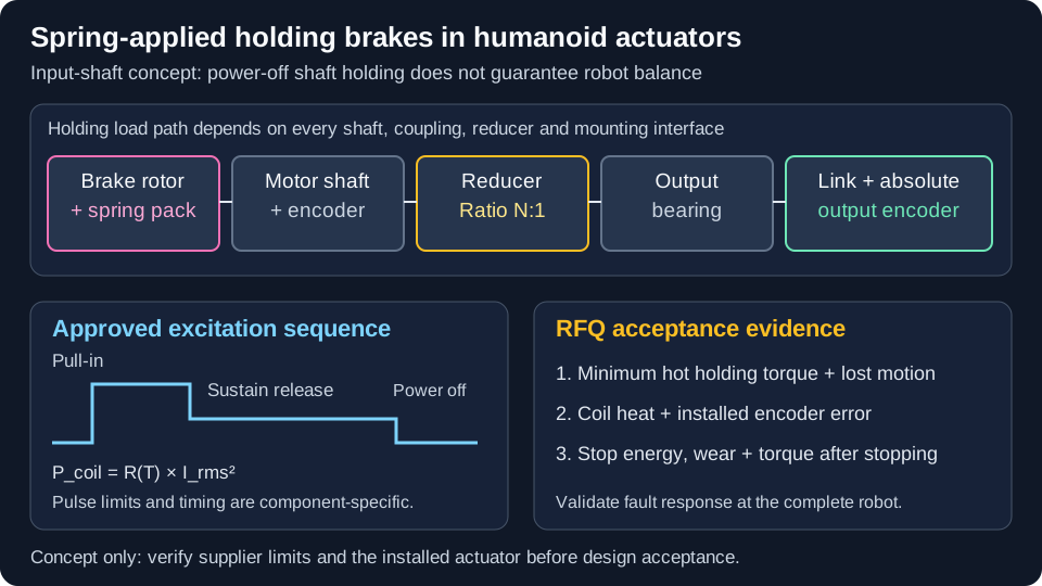
Spring-Applied Holding Brakes in Custom Humanoid Actuators: Power-Off Posture Retention, Overexcitation Thermal Budgets, and RFQ Acceptance Protocols
Specify spring-applied holding brakes for your custom humanoid actuator: compare power-off retention, thermal budgets, and FAT evidence before sending an RFQ.
Humanoid Actuator Backlash Testing: RFQ Guide for Custom Reducers
How to evaluate reducer backlash claims for custom humanoid actuators, including preload, reversal method, assembled-joint testing, encoder location, and pilot-batch evidence.