Integrated Servo Drives in Custom Humanoid Actuators: GaN vs. Silicon Inverters, Communication Bus Latency, Thermal Segregation, and PCBA Sourcing Acceptance
Compare integrated servo drives for humanoid actuators: GaN vs. silicon, bus latency, thermal limits, and PCBA acceptance. Prepare an engineering RFQ checklist.
Integrated servo drives embed the inverter power stage, gate drivers, current sensors, and real-time motion controller inside the actuator housing. This shortens motor phase leads and moves the drive out of a central cabinet. For custom humanoid actuators, the selection question is whether the reduction in harness complexity justifies tighter thermal, switching-noise, and serviceability constraints. GaN can help with high-frequency switching; silicon remains a valid choice when its measured losses and package fit meet the joint requirements.
Published and reviewed: 7 November 2026. This global English-language guide serves robotics hardware architects, embedded mechatronics leads, and procurement teams evaluating integrated rotary and linear actuators. Dimensions, currents, temperatures, and test targets below are illustrative design inputs unless attributed to a named source. The worked examples are analytical calculations, not measured factory results, product guarantees, or safety certifications. Acceptance limits require agreement for the actual motor, enclosure, battery, duty cycle, and destination market.
Executive Sourcing & Architecture Summary
- Compare complete harnesses: Local drives remove long phase and feedback runs, but DC distribution still needs branch protection, return paths, shielding, and rated connectors.
- Qualify GaN against silicon: Compare loss, current ripple, sensing settling, and electromagnetic compatibility at the same operating points. Higher PWM frequency can reduce switching-ripple capacitance; it does not remove regeneration energy storage.
- Separate heat sources and temperature limits: Reduce stator-to-PCBA coupling while providing an effective inverter-to-housing heat path. Check each component's junction, case, or ambient rating separately.
- Budget end-to-end bus latency: EtherCAT Distributed Clocks synchronize local events; clock precision alone does not establish command-to-torque latency or control bandwidth. Size CAN-FD networks from actual traffic.
- Make acceptance contractual: Specify assembly criteria, firmware revision, calibration records, and qualification versus production test coverage before approving the supplier.
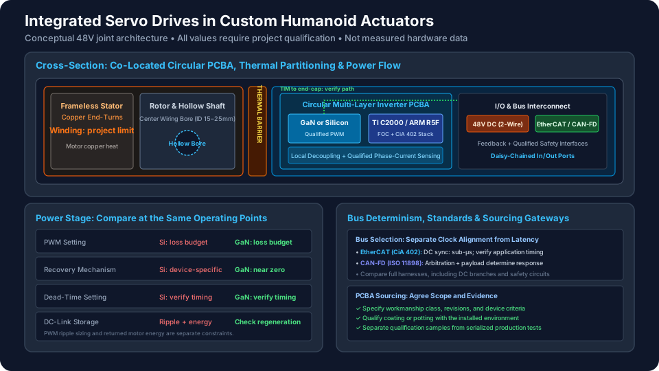
The lead illustration is a conceptual layout, not a tested product cross-section. The text and tables below explain its design and acceptance boundaries.
For an engineering review of your joint packaging and electrical specifications, submit your CAD envelope, torque-speed curves, and bus protocol requirements to our engineering inquiry desk or contact [email protected]. Explore our modular integration capabilities in custom humanoid actuator modules and frameless hollow-shaft humanoid actuators.
1. The Decentralization Imperative: Centralized Cabinets vs. Co-Located Joint Drives
In early humanoid robotic platforms, motor drives were housed inside a centralized torso or pelvic electronics bay. Three heavy copper motor phase leads, dual-encoder feedback wiring, brake lines, and thermistor cables were routed through articulated joints to reach each distal actuator.
For an illustrative humanoid with 28 to 36 degrees of freedom (DoF), compare these architecture risks:
- Harness Mass Penalty: Long phase and feedback runs add moving mass. Calculate this from the routing model rather than assuming a universal saving. For example, 96 phase conductors at 0.5 m each and 0.75 mm² copper cross-section contain about 0.323 kg of bare copper:
96 × 0.5 × 0.75 × 8.96 = 322.56 g. Insulation, shielding, connectors, and the replacement DC harness must be added before comparing architectures; this example does not establish current-carrying capacity. - High-Frequency EMI Radiation: Long phase leads carrying pulse-width modulated (PWM) voltages with nanosecond rise times (potentially fast voltage slew rates) transform the robot's wire harness into an active RF antenna. This radiates high-frequency common-mode noise into adjacent low-voltage differential signaling (LVDS) encoder buses and torque sensor leads.
- Joint Bore Congestion: Threading dozens of heavy, shielded conductors through 12 mm to 20 mm hollow-shaft bearings restricts joint range of motion, accelerates mechanical flex fatigue, and increases assembly labor during volume manufacturing.
Integrating the servo drive directly onto the actuator housing transforms the electrical interface. A simplified joint interface includes:
- A single 48V DC power bus pair (Positive and Return).
- A daisy-chained industrial fieldbus (e.g., EtherCAT input/output or CAN-FD pair).
- Safety, brake, shielding, and protective connections as required by the system design. Hardware Safe Torque Off (STO), if used, needs a qualified safety architecture; ordinary enable inputs do not establish STO compliance.
Phase leads can be shortened to fit within the joint housing. However, co-locating the drive places sensitive semiconductors, gate drivers, microcontrollers, and capacitors directly adjacent to high-temperature motor windings and high-vibration structural housings.
Illustrative Centralized Drive Architecture:
[ Torso / Pelvis Inverter Cabinet ]
      │ (3 Phase Leads: 30-60A PWM, high dv/dt)
      │ (Encoder Feedback: BiSS-C / SSI shielded pairs)
      │ (Brake Control & Temperature Lines)
      ▼ [ Heavy Limb Cable Bundle: 8-12 wires per joint x 32 joints = 250+ conductors ]
[ Actuator: Frameless Motor + Reducer + Bearings ]

Illustrative Decentralized Drive Architecture:
[ Central Battery & DC Power Distribution: 48V Bus ]
      │
      ├───────────────────────┬───────────────────────┐
      │ (48V DC Bus: 2 wires) │ (EtherCAT Daisy-Chain)│ (Safety circuits)
      ▼                       ▼                       ▼
┌─────────────────────────────────────────────────────────────┐
│ Illustrative Actuator Enclosure / Shielded Aluminum         │
│  ┌───────────────────────────────────────────────────────┐  │
│  │ Annular / Circular PCBA:                              │  │
│  │  - Real-Time MCU (FOC + CiA 402)                     │  │
│  │  - GaN or Silicon Inverter / Qualified PWM Setting    │  │
│  │  - DC-Link Decoupling + Qualified Current Sensing     │  │
│  │  - Onboard Absolute Rotor Encoder                     │  │
│  └───────────────────────────────────────────────────────┘  │
│       ▲ Low-Thermal-Resistance TIM (Heat sunk to chassis)   │
│ ══════╪════════════════════════════════════════════════════ │
│  [ Thermal Partition: Selected Polymer / Controlled Gap ]    │
│ ══════╪════════════════════════════════════════════════════ │
│  ┌───────────────────────────────────────────────────────┐  │
│  │ Motor Stator / Project-Specific Temperature Limit     │  │
│  │ Rotor + Hollow Shaft + Output Harmonic / Planetary    │  │
│  │ Output Crossed Roller Bearing + Link-Side Encoder     │  │
│  └───────────────────────────────────────────────────────┘  │
└─────────────────────────────────────────────────────────────┘
2. Inverter Power Stage Physics: Gallium Nitride (GaN) vs. Silicon MOSFETs
As an illustrative packaging brief, consider a 50 mm to 85 mm electronics cavity with 12 mm to 22 mm axial depth and a nominal 48 V supply. The actual continuous and peak phase currents must come from the motor torque constant, duty cycle, cooling boundary, and semiconductor safe operating area. A reference board's current rating cannot be scaled to a leg joint simply by using the same device family.
2.1 Reverse Recovery and Switching Losses
Silicon MOSFET body-diode reverse recovery can add turn-on loss and ringing. Enhancement-mode GaN removes that minority-carrier recovery mechanism, but output-capacitance charging, reverse conduction during dead-time, gate driving, and conduction losses remain. Select devices from loss data at the required voltage, current, and temperature rather than applying a fixed efficiency advantage to all GaN designs.
TI's TIDA-00909 reference design provides a concrete benchmark: its 48 V three-phase GaN inverter is tested up to 100 kHz PWM at 7 A RMS / 10 A peak output, with reported peak efficiency up to 98.5%. These are that reference design's conditions, not ratings for the custom joint discussed here. Silicon is not inherently restricted to 25 kHz; switching frequency follows its total loss and motor-ripple budget.
For one switch, a first-order estimate is P_sw = (E_on + E_off) × f_sw. Sum losses across all six switches and add conduction, driver, shunt, and controller power. Confirm how the datasheet defines switching energy to avoid double counting recovery or capacitance losses. Measure both candidates on the same motor and load profile before selecting one.
2.2 Dead-Time Distortion and Torque Ripple
Dead-time prevents simultaneous conduction of a half-bridge. Too much dead-time distorts average phase voltage; too little can cause destructive cross-conduction. GaN may permit shorter settings, but minimum timing depends on propagation delay, mismatch, layout, temperature, and driver configuration. The TI reference design reports a 12.5 ns dead band, so a universal requirement below 10 ns would exclude a documented implementation without proving better torque quality.
Ask the supplier for worst-case switching waveforms and measured low-speed current distortion. PWM carrier frequency, current-loop update rate, closed-loop bandwidth, and mechanical torque ripple are separate quantities. Neither a faster switch nor shorter dead-time establishes a specified mechanical bandwidth.
2.3 DC-Link Capacitors: Ripple versus Regeneration
For a deliberately simplified charge-balance example, assume a constant capacitor discharge current of 30 A for one quarter of each PWM period and allow 1 V droop. Then C = I_cap × Δt / ΔV = 30 / (4 × f_sw × 1) gives 375 µF at 20 kHz, 75 µF at 100 kHz, and 37.5 µF at 200 kHz. This is a reproducible screening calculation, not a three-phase DC-link sizing rule: actual ripple current depends on modulation, phase angle, source impedance, and motor operating point.
MLCC banks can provide compact local decoupling, but use effective capacitance after DC-bias, tolerance, and temperature derating. Check ripple heating, mechanical flex cracking, and transient voltage. Bulk polymer or electrolytic storage can remain necessary with either semiconductor technology.
Regeneration is a separate energy constraint. Absorbing an illustrative 2 J solely in a capacitor while allowing the bus to rise from 48 V to 54 V requires C = 2E / (V_max² − V_start²) = 4 / (54² − 48²) ≈ 6.54 mF. That is far greater than the switching-ripple example. Define whether the battery can accept returned energy, and what happens when its protection disconnects or it is fully charged. A braking clamp, shared bulk storage, or another verified energy sink may be required.
3. Two-Zone Thermal Segregation: Managing Stator and Electronics Limits
A joint winding may be allowed to run hotter than the nearby controller, transceiver, or capacitor. Values such as a 120°C winding target and an 85°C local board target are project choices, not universal material limits. An 85°C ambient rating is not an 85°C semiconductor junction rating. For example, TI lists the LMG5200 power stage with an operating temperature range of −40°C to 125°C; evaluate its datasheet conditions and thermal path rather than treating the whole PCBA as one temperature-rated part.
Illustrative heat-flow network, not measured temperatures:
 Motor winding -> stator -> housing -> ambient / robot link
                      |       ^
          unwanted coupling   | intended inverter heat path
                      v       |
                 PCBA -> TIM / rear end-cap
3.1 Conductive Thermal Barrier Engineering
A useful two-zone design has three elements:
- Motor heat rejection: Couple the stator to a sufficiently conductive housing region. Specify fit, contact pressure, surface finish, interface material, and measurement method. A tight mechanical fit alone does not prove a particular contact thermal resistance.
- Reduced cross-coupling: Consider a polymer partition, controlled air gap, or thermally resistive mounts between the stator and electronics. Check the selected polymer grade and reinforcement direction; do not assign the same thermal conductivity to every PEEK grade. Fasteners, phase leads, and shared housing walls still bridge the zones.
- Inverter heat rejection: Provide a short, electrically appropriate path from the power stage to an end-cap or structural heat sink. TIM thickness, contact area, compression, dielectric isolation, and aging matter alongside its quoted conductivity. Potting must not block the intended heat path or exceed component stress limits.
3.2 Thermal Verification with a Consistent Boundary
For a first-pass shared-housing model, use T_h = T_amb + (P_motor + P_inv) × R_h-a and T_j = T_h + P_inv × R_inv-h. Here R_inv-h is an effective inverter-to-housing resistance referred to the hottest junction; R_h-a represents the housing-to-ambient boundary. Accept only if T_j ≤ T_j,max − T_margin. Do not add the housing-to-ambient resistance twice or label an absolute junction temperature as a temperature rise.
For illustration, T_amb = 40°C, P_motor = 50 W, P_inv = 15 W, and R_h-a = 0.4 K/W give T_h = 66°C. If R_inv-h = 1 K/W, the estimated hottest junction is 81°C. Against a hypothetical 125°C junction limit and a project-selected 15 K margin, this screens below the 110°C design ceiling. It does not predict the MCU's local ambient or approve an 85°C-rated component.
This lumped steady-state model omits transient thermal impedance, separate housing zones, internal gradients, and variable cooling. Validate with instrumented dyno runs at the installation's worst ambient, speed, torque, and gait duty cycle. Require winding, housing, power-stage, and controller temperature channels, plus documented derating and shutdown behavior.
4. Real-Time Communication Bus Comparison: EtherCAT vs. CAN-FD vs. RS-485
A 32-axis humanoid may target 1 kHz to 4 kHz network updates, but feasibility depends on payload, topology, controller scheduling, and slave application timing. These are design targets, not bus guarantees. Keep the local current-control loop separate from the whole-body command loop.
| Parameter | EtherCAT | CAN-FD | RS-485 with an application protocol |
|---|---|---|---|
| Physical layer | Commonly 100BASE-TX industrial Ethernet. | Separate arbitration and data bit rates; 1/5 Mbps is one example. | Differential serial electrical interface; rate depends on length and transceiver. |
| Motion semantics | CoE drive profiles and supported cyclic modes must be specified. | Agree CANopen FD or proprietary objects and supported modes. | Define addressing, framing, checksums, commands, and fault handling. |
| Synchronization | Distributed Clocks can synchronize local sampling and output events. | Requires the selected protocol's synchronization and timestamp strategy. | Requires explicit polling or synchronization design. |
| Latency constraint | Frame size, topology, host deadline, and slave task timing. | Arbitration, frame length, priority, errors, and bus utilization. | Poll schedule, turnaround, framing, and retry policy. |
| Topology | Line or other supported topology; redundancy needs configuration. | Terminated multi-drop trunk; limit stubs for the chosen rate. | Terminated trunk or point-to-point; arbitrary stars need careful design. |
| Cabling | Two differential pairs for 100BASE-TX, plus required shielding/reference arrangements. | Differential pair plus required reference/shielding arrangement. | Differential pair plus required reference/shielding arrangement. |
| Controller hardware | ESC hardware or supported integrated implementation. | MCU CAN-FD controller plus suitable transceiver. | UART plus suitable RS-485 transceiver. |
| Acceptance evidence | Process-data map, clock measurements, worst-case response, fault recovery. | Traffic budget, worst-case arbitration delay, error and recovery logs. | Complete protocol specification and timing/error test logs. |
| Selection fit | Coordinated axes needing an established synchronized drive ecosystem. | Compact groups where verified bus loading meets deadlines. | Systems able to own and validate a custom motion protocol. |
4.1 What EtherCAT Distributed Clocks Establish
The EtherCAT Technology Group's technology overview, especially section 1.5, explains hardware propagation-delay compensation and synchronization substantially below 1 µs. This supports aligned local events. It does not guarantee that a command has reached the current controller within that same interval; the master must deliver data before the scheduled event.
An illustrative 4 kHz cycle allows 250 µs total. If assumed worst-case frame transport consumes 60 µs, host scheduling 40 µs, and slave application transfer 30 µs, 120 µs remains for the remaining timing margin and tasks. These assumed values demonstrate budgeting, not measured EtherCAT performance. Timestamp the actual command, sampling event, and PWM update under full traffic and fault-recovery load.
4.2 Where CAN-FD Remains Justified
CAN-FD supports larger payloads than classic CAN, but arbitration can delay lower-priority frames. Do not infer axis count from data-phase bit rate alone. For an intentionally optimistic lower bound, 32 axes exchanging separate 16-byte command and 16-byte feedback payloads at 1 kHz require 32 × 32 × 8 × 1000 = 8.192 Mbps of payload traffic. Even before headers, stuffing, arbitration, and interframe gaps, that exceeds a single 5 Mbps data phase.
Packing multiple axes into frames, reducing payloads, changing update rates, or partitioning buses changes the result. Calculate worst-case traffic with the actual protocol, include diagnostics and retries, and then choose the channel count. No universal five-to-eight-bus requirement or fixed CAN-FD jitter follows from a 32-axis label.
5. Phase Current Sensing under Fast Switching Transients
Field-Oriented Control (FOC) uses phase-current measurements and electrical rotor angle to estimate torque-producing and flux-producing current. At least two phase measurements are needed for reconstruction in a three-wire motor; a third channel adds diagnostic and sampling options. Fast common-mode transitions challenge amplifier settling, filtering, ADC timing, and layout.
5.1 In-Line Phase Shunts vs. Low-Side Sensing
- In-line sensing: A shunt in each phase provides access across more switching states. Its amplifier still needs enough common-mode range and transient recovery time for a valid ADC sample; placement does not make every instant measurable. Evaluate enhanced PWM rejection and settling from the selected amplifier's datasheet rather than assigning an isolated-modulator CMTI rating to a non-isolated current-sense amplifier.
- Low-side sensing: Ground-referenced shunts can reduce cost. Reconstruction becomes harder when valid low-side conduction windows narrow. A supported modulation strategy, synchronized sampling, and minimum-pulse management can make this topology appropriate when verified across the required envelope.
- Sourcing requirement: Specify allowable offset, gain error, drift, sample delay, and diagnostics at the agreed current and temperature points. State whether current means DC, RMS phase current, or peak phase current. Require calibration residuals and raw reference readings, not only stored coefficients.
For a reproducible loss check, a 2 mΩ shunt carrying 20 A RMS dissipates I²R = 20² × 0.002 = 0.8 W; at 60 A it dissipates 7.2 W during that pulse. The pulse duration and thermal impedance determine survivability. Kelvin connections and a low temperature coefficient help, but do not replace resistor power and pulse-rating checks.
6. Circular and Annular PCBA Packaging and Mechanical Integration
Circular and annular boards can follow the stator and reducer envelope. The sketch below is an illustrative 70 mm layout, not a released PCB or an EMC-qualified design.
Annular Circular PCBA Mechanical Layout (70 mm Outer Diameter Example):
                 ┌────────────────────────────────┐
                 │       Outer Mounting Ring      │
                 │   ┌────────────────────────┐   │
                 │   │ 48V Bus In / Out       │   │
                 │   │ [High-Current Terminals]   │
                 │   └────────────────────────┘   │
                 │  ┌──────┐            ┌──────┐  │
                 │  │ GaN  │   (Center  │ GaN  │  │
                 │  │ Ph U │   Hollow   │ Ph V │  │
                 │  └──────┘    Bore    └──────┘  │
                 │            18 mm ID            │
                 │  ┌──────┐  [Cables]  ┌──────┐  │
                 │  │ GaN  │            │ MCU  │  │
                 │  │ Ph W │            │ DSP  │  │
                 │  └──────┘            └──────┘  │
                 │   ┌────────────────────────┐   │
                 │   │ EtherCAT In / Out      │   │
                 │   │ [Micro-Lock Plus / JST]│   │
                 │   └────────────────────────┘   │
                 └────────────────────────────────┘
6.1 Annular Hollow-Bore Architecture
For a hollow-shaft joint, an annular (donut) profile can preserve the wiring bore. It does not itself permit unlimited rotation: cables still need a defined travel limit or a suitable rotary interconnect. Example packaging choices are:
- Outer Diameter (OD): Example 55 mm to 85 mm, matching the motor stator frame.
- Inner Diameter (ID): 15 mm to 25 mm hollow central bore allowing passage of the main joint shaft or multi-conductor cable harness.
- Layer Stackup: A 6-layer to 8-layer high-Tg substrate and 2 oz to 3 oz copper are possible starting points. Approve plane geometry, via arrays, insulation spacing, and temperature rise from the actual current paths; copper weight alone does not establish ampacity.
- Component Placement: Keep commutation loops short and feedback circuits away from switching nodes. Compare extracted or measured loop inductance, clearance, assembly access, and thermal paths rather than requiring an unsupported universal inductance target.
6.2 Rigid-Flex Interconnects vs. Modular Connectors
Evaluate interconnects against the envelope, assembly sequence, and measured vibration environment:
- Rigid-Flex PCB Assemblies: The inverter board is connected to the rotor encoder PCB and external I/O bulkhead via integrated flexible polyimide tails, eliminating wire crimps and vibration-sensitive internal connectors.
- Locking Connectors: Select each power, signal, and fieldbus connector for its current, temperature derating, impedance, retention, ingress, and flex-life requirements. A connector family name or latch does not establish a shock or ingress rating for the assembled joint.
7. PCBA Manufacturing and Reliability Requirements
Treat assembly acceptance, electrical function, and environmental qualification as separate evidence packages. The Global Electronics Association, formerly IPC, maintains the IPC standards ecosystem; its homepage is an entry point, not the acceptance text for a specific revision.
- Fabrication and assembly: Specify the applicable IPC-6012 board requirements and IPC-A-610 assembly criteria by agreed revision and class. Class 3 may be appropriate for a demanding program, but is not automatically mandatory for every humanoid joint. Agree solder-process requirements and device-specific workmanship addenda. A blanket 15% voiding limit or 100% CT inspection is a project requirement only when explicitly justified and contracted.
- Coating and potting: Specify the selected material, cure, coverage, cleanliness, and inspection procedure. If IPC-CC-830 qualification is required, name the agreed revision and qualified material. Coating does not establish enclosure ingress protection. Potting can improve support but also changes thermal expansion, moisture behavior, repairability, and component stress; validate it on representative assemblies.
- Calibration and traceability: Use controlled reference instruments, defined current points, and a temperature strategy. Full temperature qualification can be performed on agreed samples, with production calibration and verification at agreed points for each serial number. Preserve PCB, BOM, firmware, calibration, and test-fixture revisions together.
Before sourcing approval, ask who owns firmware source or binaries, bootloader access, parameter backups, service tools, component substitutions, and end-of-life changes. Two PCBAs with the same outline are not interchangeable if their sensor calibration, fieldbus objects, or fault response differ.
8. Sourcing Checklist: 10-Point RFQ Specification for Integrated Humanoid Actuator Drives
Use this checklist to turn an architecture discussion into a quoteable scope. Values must be agreed against the real joint and battery configuration.
- 1. DC bus and regeneration: State nominal, minimum, fully charged, and transient voltages; return-energy path, clamp behavior, protection, and safety assessment. A nominal 48 V label does not establish SELV compliance.
- 2. Current and duty cycle: Define continuous RMS phase current, peak amplitude, peak duration, repetition, torque-speed points, ambient temperature, and cooling fixture. Do not assume a fixed peak multiplier.
- 3. Power stage: Allow GaN or silicon if the supplier demonstrates the agreed loss, ripple, envelope, and EMC targets. Record device ratings, PWM setting, and derating.
- 4. Fieldbus timing: Name EtherCAT CoE, CANopen FD, or the custom protocol; supported operating modes, payload map, node count, update deadline, synchronization tolerance, and fault response.
- 5. Thermal limits: Distinguish winding temperature, board-local ambient, case temperature, and junction temperature. Request measurement locations, thermal model assumptions, continuous derating, and shutdown thresholds.
- 6. Current sensing: Specify topology or the required measurement performance; request settling-time evidence, calibrated error bounds, and temperature coverage.
- 7. Feedback interfaces: Identify rotor and output encoder types, resolution versus installed accuracy, electrical interfaces, timing, redundancy, and power-up behavior.
- 8. Mechanical envelope: Supply STEP geometry, hollow bore, mounting pattern, datum scheme, cable bend space, connector access, grounding, and thermal contact requirements.
- 9. Environmental qualification: Agree workmanship class and revisions, coating or potting, vibration spectrum, shock pulses, humidity exposure, sample count, and pass/fail criteria.
- 10. Acceptance deliverables: Separate design qualification, lot sampling, and serial-number production tests. Request raw data, calibration traceability, firmware/BOM revisions, nonconformance handling, and change notification.
For a practical review, attach this completed checklist to your joint CAD and duty cycle when contacting the engineering inquiry desk. Identify unresolved limits explicitly so the supplier can quote engineering work and validation separately from production units.
9. Architectural Comparison: External Drives vs. Integrated Silicon vs. Integrated GaN
This matrix compares selection considerations, not measured products. Both silicon and GaN can meet a joint requirement when the full design is qualified.
| Architecture dimension | External cabinet drive | Integrated silicon drive | Integrated GaN drive |
|---|---|---|---|
| Packaging | Central electronics volume; service access can be easier. | Joint-local PCBA and connector constraints. | Same constraints; smaller switching circuitry may help. |
| PWM selection | Motor, cable, device loss, and EMC set the frequency. | Verify silicon loss at the selected frequency. | Higher frequency may be practical; validate total system loss. |
| Recovery loss | Depends on the chosen semiconductor. | Body-diode recovery depends on device and commutation. | No minority-carrier body-diode recovery; other losses remain. |
| Dead-time | Driver and layout dependent. | Tune and compensate from measured waveforms. | Shorter settings may be possible; verify worst-case timing. |
| DC-link storage | Local ripple filtering plus system energy management. | MLCC, polymer, or electrolytic combinations as required. | Compact MLCC decoupling possible; regeneration still needs an energy path. |
| Harness | Long phase and feedback runs. | Short phase leads; shared DC and communication distribution. | Same architectural harness benefit as integrated silicon. |
| Thermal coupling | Separate drive cooling can simplify motor heat isolation. | Motor and inverter compete for housing heat rejection. | Potential switching-loss benefit; thermal isolation still required. |
| Control response | Depends on sensing, firmware, network, and mechanics. | Measure command-to-current and torque frequency response. | Faster switching alone does not establish higher torque bandwidth. |
| Lifecycle cost | Compare cabinet space, cabling, assembly, and repair. | Compare custom NRE, test fixtures, yield, and service replacement. | Add device cost, layout sensitivity, qualification, and sourcing risk. |
10. Factory Acceptance and Qualification Matrix
The seven rows below are a proposed acceptance framework, not a claim that a supplier or product has passed these tests. Agree limits before purchase. Design qualification and destructive or extended environmental tests generally use an agreed sample plan; production FAT checks use the released, repeatable serial-number test procedure.
| Inspection item | Method and equipment | Conditions to specify | Acceptance basis | Supplier deliverable |
|---|---|---|---|---|
| 1. Electrical insulation and grounding | Approved insulation-resistance, dielectric, and bonding procedures where applicable. | Insulation diagram, chassis connections, circuits disconnected, voltage, duration, environment. | Safety assessment and released design procedure; do not apply a generic 500 V test to connected electronics. | Serial result with procedure revision and actual readings. |
| 2. Phase-current measurement | Calibrated source/load and reference current measurement. | Positive/negative current points, full-scale definition, temperatures, uncertainty. | Agreed offset, gain, linearity, and drift limits; coefficients alone are insufficient. | Calibration table, residuals, uncertainty, and serial identifier. |
| 3. Continuous torque and thermal rise | Dyno, torque transducer, speed measurement, and temperature channels. | Torque-speed points, ambient, cooling boundary, duration, stabilization criterion. | Rated output without exceeding each component's derated limit; verify current limiting and thermal shutdown. | Time-series torque, speed, current, voltage, temperatures, and fixture description. |
| 4. Switching and protection | Suitable-bandwidth scope, correctly rated differential and current probes. | Maximum bus, regeneration, current, temperature, probe setup, and fault cases. | Device voltage margins, gate limits, ringing, protection response, and EMC plan; no minimum slew rate is inherently desirable. | Waveforms with probe bandwidth, test points, and operating conditions. |
| 5. Fieldbus and application timing | Protocol logs plus hardware timestamps at sampling/PWM boundaries. | Full node count, payload, deadlines, diagnostics, error injection, firmware revisions. | Separate clock alignment, worst-case command latency, missed deadlines, and recovery limits. | Timing distributions, maxima, error counters, and configuration files. |
| 6. Shock and vibration qualification | Instrumented fixture and agreed shaker/shock profiles. | Measured service spectrum, mounting axes, duration, pulse shape, sample plan. | Agreed powered continuity and pre/post functionality; define inspection coverage and sample size. | Profile traces, continuity logs, functional results, and failure analysis. |
| 7. Solder and assembly inspection | AOI, X-ray where needed, and documented workmanship checks. | Critical joints, process capability, device supplier guidance, coverage and sampling. | Contracted IPC class/revision and device-specific criteria; voiding limits must be justified. | Inspection images, measured defects, disposition, and traceable lot records. |
Do not copy a shock peak into a random-vibration RMS specification: the load mechanisms and exposure durations differ. Likewise, a zero-error communication run supports only the tested setup and duration; it does not prove a safety integrity level or universal reliability.
11. Frequently Asked Questions
Why choose 48 V rather than 24 V or 96 V?
Select voltage from the battery range, motor winding, regeneration, insulation, and system safety assessment. At equal input power and efficiency, doubling DC voltage halves average DC input current. With the same cable resistance this quarters cable I²R loss, but it does not automatically halve motor phase current or reduce harness mass by 75%. A nominal 48 V bus alone establishes neither SELV nor compliance for global markets.
Do short phase leads make fast GaN edges harmless to motor insulation?
Short leads reduce transmission-line effects, but do not eliminate local ringing, common-mode currents, bearing currents, or winding stress. Validate switch-node and motor-terminal waveforms with the actual motor, layout, cable, and edge-rate setting. Thermal insulation class is distinct from repetitive impulse and inverter-duty capability; specify both from the winding supplier rather than treating a class letter as proof.
Can an integrated actuator operate without potting?
Yes, if its mounting, cleanliness, coating, enclosure, and thermal design pass the agreed environment. Potting can support components but adds mass, complicates repair, and can impose thermal-expansion stress. Compare coated and potted samples under representative shock, vibration, humidity, and temperature cycling before choosing the production process.
Does sub-microsecond EtherCAT synchronization guarantee a 4 kHz torque loop?
No. Distributed Clocks align local events, while network transport, host scheduling, slave firmware, sensing, PWM timing, and mechanics determine response. A 4 kHz command cycle allows 250 microseconds; demonstrate a worst-case timing budget at the real node count and payload. Measure closed-loop torque bandwidth separately from the command update rate.
How should onboard encoder interference be accepted?
Test installed angular error and fault behavior across rotor position, phase current, temperature, and switching conditions. Magnetic shielding, placement, or an alternative sensing principle may help, but immunity cannot be inferred from sensor type alone. Specify installed accuracy and diagnostic behavior in addition to nominal encoder resolution.
Will an integrated GaN drive reduce total actuator cost?
It may reduce harness and packaging work, but custom PCBA NRE, power devices, EMC development, fixtures, calibration, yield, and complete-joint replacement can offset those savings. Compare silicon and GaN quotes at prototype, pilot, and volume quantities using the same acceptance scope. Require an itemized cost model rather than a universal labor-saving percentage.
12. Conclusion & Sourcing Next Steps
Integrated servo drives can simplify a humanoid's electrical architecture when motor, electronics, and housing are developed together. Choose GaN when the demonstrated switching-loss and packaging benefits justify its cost and validation effort. Choose silicon when it meets the same joint requirements with an acceptable thermal and ripple budget.
Before freezing tooling, close three evidence gaps: measured performance at the required duty cycle, worst-case command and feedback timing, and a released PCBA acceptance plan. Keep unverified items open in the RFQ rather than converting example values into supplier guarantees.
To initiate an engineering feasibility review for your custom joint architecture, send your 3D CAD envelope, continuous and peak torque-speed profiles, DC bus parameters, and preferred fieldbus specifications to our engineering team at [email protected] or contact our engineering inquiry desk.
Explore related technical frameworks across our custom actuator portfolio:
- Custom Humanoid Actuator Modules: Complete integrated rotary and linear joint assemblies.
- Frameless Hollow-Shaft Humanoid Actuators: High-torque density frameless motors with central bore integration.
- Custom Actuator Housings and Interfaces: Precision CNC 7075-T6 structural enclosures and thermal barriers.
- Funded Humanoid Prototype Programs: Accelerated engineering and pilot production for commercial humanoid developers.
Sources & Reference Boundaries
- Texas Instruments: TIDA-00909 GaN inverter reference design — Specific published reference-board operating conditions, PWM frequency, efficiency, dead band, and shunt-based sensing. Its results do not validate a higher-current custom actuator.
- Texas Instruments: LMG5200 power-stage product information — Device architecture, near-zero reverse recovery, package, voltage/current limits, and listed temperature range. Check the linked datasheet against the released BOM before design approval.
- EtherCAT Technology Group: EtherCAT technology overview, section 1.5 — Distributed Clocks, propagation-delay compensation, and the distinction between aligned local events and telegram delivery time.
- Global Electronics Association / IPC standards ecosystem — Organizational entry point for IPC standards and certifications. This homepage is not the text of IPC-A-610, IPC-6012, or IPC-CC-830 and does not establish a numeric solder, shock, or production acceptance threshold.
Reference review date: 7 November 2026. The capacitor charge/energy examples, shared-housing thermal model, traffic arithmetic, RFQ checklist, and acceptance matrix are analytical procurement aids. No first-party hardware test data or certification is claimed. Resolve standard editions, jurisdictional safety obligations, device limits, test uncertainty, and acceptance ownership in the project-specific design and purchase documents.
Author

Categories
More Posts
Dual-Encoder Architecture in Humanoid Joint Actuators: Link-Side vs. Motor-Side Sensing, Elastic Deflection Compensation, and RFQ Acceptance Protocols
Compare dual-encoder architecture for humanoid joints: motor vs link sensing, torque-estimation limits and calibration tests. Prepare an actuator RFQ.
Inverted Planetary Roller Screws vs. Ball Screws in Humanoid Linear Actuators: Sourcing, Dynamic Load, and Life-Cycle Engineering
Compare inverted planetary roller screws vs ball screws for humanoid actuators. Check loads, life assumptions and RFQ evidence before requesting a quote.
Hollow-Shaft Cable Routing in Custom Humanoid Actuators: Bore Sizing, Torsion Fatigue Life, Multi-Conductor EMI Shielding, and Sourcing Acceptance Protocols
Master hollow-shaft cable routing for humanoid actuators: bore sizing, torsion fatigue limits, EtherCAT/phase EMI shielding, and supplier RFQ acceptance.