Hollow-Shaft Cable Routing in Custom Humanoid Actuators: Bore Sizing, Torsion Fatigue Life, Multi-Conductor EMI Shielding, and Sourcing Acceptance Protocols
Master hollow-shaft cable routing for humanoid actuators: bore sizing, torsion fatigue limits, EtherCAT/phase EMI shielding, and supplier RFQ acceptance.
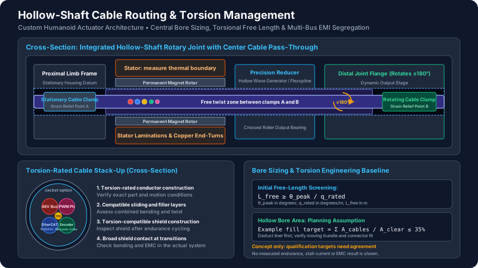
Hollow-shaft cable routing in custom humanoid actuators reduces exposed cable loops, but bore size alone does not establish harness reliability. Choose the cable schedule, joint travel, usable twist length, shielding interfaces, and temperature envelope together. A large bore cannot compensate for an unsuitable torsion rating, poor strain relief, or a noisy termination.
Published and reviewed: 10 November 2026. This English-language guide serves global humanoid robotics hardware architects, harness reliability engineers, and technical sourcing teams. Its scope is bounded-travel rotary joints carrying power, feedback, and communication cables. Unlimited rotation needs a separately qualified rotary interconnect. Examples and acceptance targets below are engineering planning aids, not measured product results, supplier guarantees, or evidence of regulatory compliance. No first-party endurance dataset is claimed; release requires project-specific qualification and applicable local electrical-safety review.
1. Executive Sourcing & Engineering Summary
- Cable selection: A drag-chain flex rating does not establish suitability for cyclic twist. Require the exact cable part number and its torsion, temperature, bend-radius, and endurance conditions.
- Bore sizing versus torque density: Use finished cable diameters and the smallest clear passage through the assembled joint. The 35% fill factor used here is an initial packaging assumption to validate, not a universal standard.
- Torsional free length: Calculate angular excursion from the installed neutral position. A cable specified at ±180°/m corresponds to ±1.8°/cm, not ±360°/m. Match this rating to the supplier's complete test conditions.
- EMI co-location: Preserve differential-pair geometry, separate switching circuits where practical, and define shield termination and equipotential bonding before freezing connectors.
- Thermal ampacity: Measure the harness environment and apply the cable manufacturer's installation-specific current guidance. Stator temperature alone cannot establish conductor temperature or current capacity.
- Contractual acceptance: Separate design qualification from production screening. Agree the mission cycle, failure criteria, sample count, and evidence package before quoting a lifetime requirement.
For a comprehensive mechanical and packaging review, submit your joint CAD envelopes, cable bundle schedules, and kinematic travel angles to our engineering inquiry desk. You can also evaluate our standard frameless hollow-shaft humanoid actuators and custom humanoid actuator modules.
2. The Kinematic Dilemma: Why External Dress Packs Fail in Humanoid Limbs
Early-stage humanoid prototypes frequently utilize external cable dress packs—routing corrugated conduits or braided split sleeves outside the joint structural frame. While this approach simplifies benchtop prototyping, its suitability must be reassessed as robots transition to dynamic locomotion and close-quarters interaction. A protected, qualified external route can remain a valid production choice.
External Dress Pack Failure Mechanisms:
1. Dynamic Snagging: Loops catch on external environmental objects or structural frame edges.
2. Pinching & Crushing: Multi-axis joint travel pinches harnesses at mechanical end-stops.
3. Variable Lever Arms: External loops shift center-of-mass and apply unpredictable parasitic torques.
4. Cowling Interference: Body panels rub against cables, causing abrasive jacket failure.

Hollow-Shaft Pass-Through Solution:
Concentric Joint Routing: Cable runs along the neutral axis of rotation (θ_joint).
Twist Zone Defined: Bending and torsion still need evaluation at bore exits and clamps.
Environmental Protection: Depends on housing seals, glands, and service openings.
However, internal hollow-shaft routing introduces cyclic torsional deformation, often combined with exit bending and contact friction. When a cable bends over a pulley or in a drag chain, outer conductors experience tension while inner conductors experience compression, which can be mitigated by flexible conductor stranding. In contrast, when a cable twists along its central longitudinal axis, the internal layers redistribute strain according to their lay, friction, and restraint.
A homogeneous circular-shaft approximation illustrates how radius and free length affect shear strain (gamma):
gamma = r × theta / L_freeWhere:
gammais the shear strain on the outermost cable element (dimensionless).ris the outermost radius of the cable bundle or individual conductor (r = d/2).thetais the relative joint rotation angle between stationary and rotating clamps (in radians).L_freeis the unconstrained free length over which the twist is distributed (in millimeters).
This approximation is not a cable fatigue-life model: a stranded, layered harness can slip internally and twist nonuniformly. Do not infer cycle life from a generic allowable copper strain. Use the manufacturer's twist rating q_rated and qualified installation geometry for initial screening:
q_peak = theta_peak / L_free
L_free ≥ theta_peak / q_rated
Here theta_peak is the largest absolute angle from the installed neutral position, in degrees, and length is in meters. Keep peak excursion separate from peak-to-peak sweep. For example, a centered joint moving from −180° to +180° has 180° peak excursion and 360° sweep.
Worked torsion example: With 0.10 m usable free length, that joint imposes ±1,800°/m, or ±18°/cm. Relative to a ±180°/m rating, this is ten times the rated excursion per length. The same screening calculation requires 1.0 m free length at that rating; the actuator's 100 mm axial length is insufficient. A cable rated at 360°/m would correspond to 3.6°/cm, not 1.8°/cm.
The igus CFROBOT product table illustrates why ratings need conditions: its five-million-cycle column lists ±180°/m within a stated temperature band, while higher cycle columns use smaller twist excursions. This is manufacturer data for that cable series, not proof of installed humanoid harness life.
If the required length cannot fit, reduce travel, relocate anchor points, or investigate a qualified loop cartridge or rotary interconnect. A folded path does not automatically provide uniformly active twist length. Record neutral orientation, clamp spacing, combined bending, motion speed, and assembly pre-twist in the qualification fixture drawing.
3. Inner Clear Bore Sizing & Fill Factor Mechanics
Specifying the inner diameter (ID) of a custom hollow-shaft actuator requires balancing electromagnetic motor performance against harness packaging physics.
3.1 The Electromagnetic Sizing Trade-Off
A larger passage can compete with rotor support, bearing sections, reducer geometry, or stator space within a fixed outer envelope. The effect depends on motor topology; an increase in bore does not imply a fixed percentage torque penalty.
For a simplified cylindrical air gap with uniform tangential shear stress tau_gap, torque scales as:
T ≈ 2 × pi × tau_gap × r_airgap² × L_stackThis relation explains sensitivity to radius and stack length; it does not predict the thermal torque of a redesigned motor. Ask suppliers to compare candidate bore sizes at the same housing envelope, cooling boundary, current limit, and winding-temperature limit. Retain the resulting torque-speed and thermal evidence with the interface drawing.
3.2 A 35% Cross-Sectional Fill Factor Planning Example
For initial packaging, this guide assumes cable area occupies no more than 35% of the net clear bore area. This is a proposed design target, not a standard-mandated limit or a guarantee against jamming:
Fill factor = sum(d_i²) / D_clear²
Example target: fill factor ≤ 0.35
D_clear ≥ sqrt(sum(d_i²) / 0.35)
Where:
d_iis the outer diameter of each individual cable or jacketed sub-bundle.D_clearis the net clear diameter of the hollow shaft after accounting for internal protective sleeves, snap rings, and bearing retention shoulders.
Clear Bore Area Allocation Breakdown:
┌─────────────────────────────────────────────────────────────────┐
│ Net Clear Bore Internal Cross-Section (100% Total Area)         │
├───────────────────────────────┬─────────────────────────────────┤
│ Active Cable Cross-Section    │ Free Air Clearance & Torsion    │
│ (Example 35% Fill Target)         │ Relief Zone (Example 65% Space)│
│ - DC Bus Power Pairs          │ - Allows radial expansion during│
│ - PWM Motor Phase Leads       │   reverse twist cycles          │
│ - EtherCAT Shielded Pairs      │ - Measured after protective     │
│ - BiSS-C Encoder Lines        │   liner thickness is deducted    │
│ - 24V Brake Lines             │ - Prevents internal wedging     │
└───────────────────────────────┴─────────────────────────────────┘
How to use the target: Include insulation, shields, and jackets in every diameter; bare copper area is insufficient. For a finished hybrid cable, use its complete outer diameter once rather than adding internal cores again. Empty area does not establish cooling, and area arithmetic does not establish that connectors or a deformed bundle will pass.
Worked bore example, assumed diameters: This schedule represents a routing concept that carries both a DC bus and downstream motor phases. With an integrated drive, some phase conductors may remain local and can be removed from the through-bore schedule.
| Through-bore circuit | Quantity | Finished diameter each | Contribution to sum of squared diameters |
|---|---|---|---|
| DC supply | 1 | 3.5 mm | 12.25 mm² |
| DC return | 1 | 3.5 mm | 12.25 mm² |
| Motor phases U/V/W | 3 | 3.0 mm | 27.00 mm² |
| Shielded Ethernet cable | 1 | 5.5 mm | 30.25 mm² |
| Shielded encoder cable | 1 | 4.0 mm | 16.00 mm² |
| Brake leads | 2 | 2.0 mm | 8.00 mm² |
The sum is 105.75 mm². Thus D_clear ≥ sqrt(105.75/0.35) = 17.38 mm. An 18 mm clear passage gives 32.6% area fill. A 0.5 mm radial liner requires at least 19 mm machined diameter before tolerances, runout, retention shoulders, or other intrusions are allowed for. An 18 mm connector envelope still needs insertion clearance; use a larger passage, removable termination, or a documented assembly sequence if it cannot pass.
Freeze the minimum assembled passage, not just the nominal shaft machining dimension. Check the bundle envelope throughout motion, the smallest local throat, liner retention, and connector service access in a physical mock-up before tooling release.
4. Routing Architecture Comparison: Solid vs. Hollow vs. Slip Rings
Robotics engineering teams have five primary architectural options for routing power, communication, and feedback across rotary joints. The optimal selection depends on the required kinematic range of motion, service life expectations, and unit cost targets.
| Joint Architecture | Travel Boundary | Main Benefit | Main Qualification Risk | Procurement Decision |
|---|---|---|---|---|
| Solid shaft with external dress pack | Limited by protected loop geometry | Accessible assembly and service | Snagging, pinching, and exit bending | Retain when the swept route can be protected and tested. |
| Concentric hollow shaft | Bounded rotation within cable rating | Compact protected passage | Local twist and hidden chafing | Use when both clear bore and active free length fit. |
| Oversized hollow bore | Still limited by cable twist rating | More cable and connector clearance | Motor, bearing, mass, and cost trade-offs | Request a like-for-like actuator performance comparison. |
| Twist capsule or coiled loop | Finite travel defined by cartridge | Stores controlled cable movement | Combined bending, winding limits, replaceability | Evaluate when a straight free-length zone cannot fit. |
| Electrical slip ring | Continuous rotation within product ratings | Removes accumulating cable twist | Contact wear, current heating, Ethernet compatibility | Obtain a specified power/data model and system-level test evidence. |
4.1 When to Choose a Hollow Shaft Over a Slip Ring
For bounded joint motion, start by checking whether a passive harness can meet twist, bend, temperature, and service requirements. It avoids sliding electrical contacts but may require substantial free length inside the limb.
A slip ring can be justified for unlimited rotation or for packaging that cannot support a qualified flex route. Do not assume all slip rings corrupt Ethernet: use a model explicitly supporting the intended physical layer and verify it with the actual drive, cable lengths, and rotation profile. Ask about rated current per circuit, contact resistance variation, service interval, contamination control, and replacement access. Compare installed cost and maintenance, rather than applying generic price premiums or cycle-life rankings.
5. Torsion-Rated Cable Engineering: Layer-by-Layer Construction
A continuous-flex cable for a linear carrier may lack a torsion rating. Cable construction matters, but a named strand class or jacket material alone cannot predict endurance. Evaluate the complete cable and termination assembly under combined motion.
Illustrative robotic harness layers (supplier designs vary):
Outer jacket -> torsion-compatible shield -> sliding/filler layers
             -> insulated, stranded power or signal conductors
Keep differential pairs intact; provide separate mechanical strain relief.
5.1 Conductor Stranding & Lay Pitch
Request conductor cross-sections, strand construction, lay arrangement, and permitted installation conditions from the cable maker. Fine stranding helps flexibility, but neither a universal strand diameter nor a lay pitch of less than eight diameters proves torsion performance. Require documented twist capability for the selected size and circuit mix. Substituting a conductor or shield can change mechanical behavior and invalidate the original qualification.
5.2 Low-Friction Sliding Buffers (PTFE Wrapping)
Some robotic cables use sliding tapes and fillers to accommodate internal motion. PTFE or FEP may be suitable, but they are design options rather than mandatory ingredients. Confirm compatibility with the jacket, assembly process, temperature, lubricants, and intended movement. A sleeve added during joint assembly does not convert an ordinary cable into a torsion-rated cable.
5.3 Torsion-Optimized Shielding
A braid, served shield, or foil assembly must retain electrical and mechanical performance after repeated twist. Ask for the shielding construction, termination method, and post-endurance inspection evidence. Inspect for broken shield strands, bunching, exposed foil edges, and damage at connector transitions. Optical coverage by itself does not establish high-frequency shielding effectiveness or installed fatigue life.
5.4 Outer Jacket Formulation
Select jacket material against the actual temperature, oil, abrasion, flame, and environmental requirements. PUR and TPE are common options; material names alone do not establish suitability. Where a halogen-free construction is required, specify that requirement explicitly and obtain evidence for the selected part. Avoid universal material prohibitions unsupported by the installation specification.
6. Multi-Conductor EMI Segregation in Confined Metallic Conduits
Confined routing can place differential communication and encoder lines beside switching power circuits. A metal bore does not by itself isolate cables from one another. Keep motor phases and brake switching loops separate from sensitive pairs where space permits; maintain the intended pair twist and connector pin assignment.
Illustrative functional grouping, not a certified cable construction:
[DC supply and return]  [U/V/W phases]  [switched brake pair]
[shielded Ethernet pairs]              [shielded encoder pairs]
All groups: check insulation, bending, torsion and termination boundaries.
6.1 Coupling Physics: Capacitive & Inductive Crosstalk
The relevant noise sources are switching-edge voltage and current changes, not only bus voltage or PWM frequency. Obtain or measure the actual drive edge behavior and circuit geometry rather than assuming a universal slew rate.
- Capacitive (Electric Field) Coupling:
I_noise = C_mutual × dV/dtWhereC_mutualis the parasitic capacitance between the motor phase wire and the adjacent communication pair. With highdV/dt, substantial displacement currents are injected directly into the data lines. - Inductive (Magnetic Field) Coupling:
V_noise = M × dI/dtWhereMis the mutual inductance between loops. High phase switching currents induce transient differential voltage spikes across unshielded signal pairs, potentially reducing receiver noise margin. Magnitude depends on loop geometry, shielding, termination, and receiver design.
6.2 Structural Mitigation Requirements
- Control loop area: Keep DC supply and return close together and group three motor phases in a compact arrangement approved by the drive and cable suppliers. Star-quad is a four-conductor geometry, not a universal prescription for U/V/W. Geometry reduces coupling; it does not guarantee field cancellation.
- Preserve communication construction: Use an appropriate shielded Ethernet cable and preserve pair geometry through connectors. SF/UTP describes overall braid and foil with unshielded individual pairs; S/FTP combines an overall braid with individually foil-shielded pairs. Do not treat the two as identical or demand one without considering motion and electrical qualification.
- Define shield interfaces: Beckhoff's shielding guidance recommends broad, low-impedance connections and circumferential contact at transitions. Avoid long pigtails. Address equalizing currents through the system bonding design and keep shield contact separate from mechanical strain relief. DC continuity alone cannot demonstrate high-frequency shielding performance.
- Coordinate brake suppression: Select clamp circuitry and placement with the brake and drive suppliers. A simple flyback diode can delay brake engagement; confirm release and application timing under the intended safety architecture.
For a packaging review before connector selection, share the cable schedule and shield-interface drawing with the engineering inquiry desk. Identify which circuits cross the bore and which remain local to the integrated drive.
7. Thermal Boundaries, Friction Wear, and Strain Relief DFM
The internal environment of a custom humanoid actuator is mechanically and thermally aggressive. Sourcing teams must ensure the harness assembly is designed for manufacturing (DFM) and protected against wear.
7.1 Stator Conduction & Harness Temperature Derating
The winding, shaft, housing, and conductor temperatures differ. Establish harness temperature using measurements under the actual duty cycle and cooling boundary, including hot restart and sustained load. Do not assume an internal bore temperature from a generic stator value.
For preliminary calculations, a supplier may provide installation-specific factors:
I_allowable = I_catalog × f_temp × f_groupCheck that the catalog baseline and factors use compatible assumptions and do not double-count derating. Illustrative arithmetic only: a 15 A baseline multiplied by assumed factors of 0.75 and 0.70 gives 7.875 A. These factors are not extracted standard limits and do not establish an 18 AWG rating. Validate conductor, insulation, connector, voltage drop, and temperature-rise constraints together.
IEC 60204-1:2016+A1:2021 addresses machine electrical equipment, including protection and bonding. Its public catalog description does not establish a humanoid cable lifetime, a universal bundling factor, or the FAT thresholds proposed here. The responsible electrical engineer must determine applicable clauses, editions, and local requirements.
7.2 Anti-Chafing Liners & Chamfer Radii
- Bore transitions: Remove burrs and provide smooth, radiused entries matched to the cable bend and contact conditions. Specify the actual radius, finish, and inspection method on the released drawing instead of assuming one minimum suits every jacket.
- Internal sleeving: Assess a retained PTFE/FEP liner or another compatible wear barrier if rubbing cannot be eliminated. Deduct its wall thickness from clear bore, check creep and migration, and avoid adhesive or press-fit arrangements that obstruct service or reduce clearance.
- Fastener clearance: Include retaining rings, bearing nuts, encoder hardware, and tolerance stack-up in the minimum passage inspection. Teardown should inspect both the cable jacket and liner for localized wear.
7.3 Rotational Strain Relief Clamping
Define a stationary clamp on the proximal structure and a rotating clamp on the distal flange. Mark the cable's neutral orientation and document the active length between restraints. Follow the cable and clamp suppliers' permitted compression rather than applying an unsupported universal 15% limit. Verify retention under motion without crushing the insulation or using the shield as the load-bearing element. Keep bend radius controlled at clamp exits, and make replacement repeatable through orientation marks and assembly instructions.
8. Sourcing & Integration Checklist: 10-Point RFQ Specification
When issuing a Request for Quotation (RFQ) for custom hollow-shaft actuators or pre-integrated mechatronic joint modules, provide this technical specification checklist to prospective manufacturing partners:
- 1. Motion envelope: State neutral position, peak excursion, total sweep, angular speed, acceleration, dwell, emergency-stop motion, and combined bending.
- 2. Clear passage: Provide the minimum assembled bore, tolerance stack, liner thickness, and connector pass-through envelope.
- 3. Cable schedule: List each circuit, finished diameter, current, voltage, shielding, and connector. Treat 35% fill as an initial target subject to physical routing checks.
- 4. Active twist length: Compare
theta_peak / L_freewith the exact cable rating. For example, 180°/m equals 1.8°/cm. Record installed pre-twist. - 5. Cable identity: Require part numbers, construction revision, temperature and motion ratings, and advance notification of substitutions.
- 6. Sliding and wear interfaces: Identify liners, fillers, grommets, lubricant compatibility, and inspectable chafing locations.
- 7. EMC interfaces: Freeze pair routing, shield contact, bonding, and brake-suppression design with system-level test criteria.
- 8. Thermal evidence: Supply duty cycle and cooling boundaries; request current-capacity, voltage-drop, connector, and temperature-rise checks.
- 9. Assembly and service: Define clamp position, permitted compression, neutral-orientation marks, threading order, and replacement procedure.
- 10. Lifetime and acceptance: Define a full cycle, sample count, mission-based target, monitoring bandwidth, failure limits, and raw-log deliverables. A proposed five-million-cycle target requires supplier agreement and relevant qualification evidence.
9. Factory Acceptance Test (FAT) & Quality Validation Matrix
Use the following matrix to negotiate an acceptance plan, not as a claim that a named standard mandates these numbers. Qualification challenges the design under representative conditions; production screening checks assembled units without consuming their intended fatigue life. Agree sample size, lot sampling, and release authority in the quality plan.
Define one torsion cycle explicitly, for example neutral → positive limit → negative limit → neutral. Record amplitude, frequency, speed, acceleration, temperature, free length, bend geometry, cable revision, and pretwist. Accelerating a test by raising speed or temperature needs justification because it can change the failure mechanism. A single surviving specimen does not demonstrate a population reliability or confidence level.
| Test Parameter | Purpose & Method | Proposed Acceptance Basis | Frequency & Evidence |
|---|---|---|---|
| 1. Torsion endurance | Cycle the installed harness geometry with representative combined motion and thermal boundary. Monitor electrical continuity. | Mission-derived cycle count; five million may be a negotiated example, not a universal guarantee. No detected discontinuity at the agreed monitoring resolution. | Design qualification; fixture drawing, sample identities, cycle definition, failure logs, and teardown photographs. |
| 2. Conductor resistance drift | Four-wire measurement before and after cycling at a controlled reference temperature. | A proposed limit such as less than 5% drift must account for instrument uncertainty and conductor temperature. | Qualification checkpoints; retain raw readings and temperature correction. Continuity needs separate dynamic monitoring. |
| 3. Dielectric withstand | Test defined insulation barriers with a validated fixture and isolated harness. | Voltage, duration, leakage limit, and ramp specified by the applicable product requirements and component ratings. | Agreed qualification and production plan; disconnect vulnerable electronics and follow controlled discharge procedures. |
| 4. Insulation resistance | Measure specified conductor-to-conductor and conductor-to-shield combinations after agreed conditioning. | Test voltage and resistance limits approved for the cable and connected components; no generic 500 V prescription. | Qualification and agreed outgoing screening; record environment, test circuit, and instrument calibration. |
| 5. EtherCAT integrity under switching load | Exercise representative motion, acceleration, regeneration, and brake switching within drive thermal and peak-duration limits. | A proposed zero-error window must state duration, network configuration, frame count, diagnostic counters, and instrument sensitivity. | System qualification and pilot checks; retain master/slave CRC, link-loss and working-counter diagnostics. Do not sustain peak-current stall for a 12-hour run. |
| 6. Shield and bonding continuity | Inspect circumferential contact and measure bonding using the approved method and reference points. | Drawing-defined resistance limit and workmanship acceptance. DC resistance does not qualify high-frequency attenuation. | Production inspection plus EMC qualification; retain readings and termination photographs. |
| 7. Jacket and liner wear | Inspect contact points and dismantle selected endurance samples. | No exposed conductor or shield, through-wall damage, or interference with motion; agree measurable wear limits before testing. | Qualification teardown and defined production visual checks; photographs, dimensions, and disposition record. |
For sourcing approval, request a traceable report rather than a pass stamp: cable and connector bill of materials, fixture revision, test software settings, calibration records, raw logs, failure disposition, and any deviations from your mission profile. Agree corrective-action and requalification triggers for cable, shield, liner, clamp, or connector changes. A factory test report is evidence for the tested configuration; it is not blanket safety certification or a lifetime warranty.
10. Frequently Asked Questions (FAQ)
Does a drag-chain flex rating establish hollow-shaft torsion life?
No. Linear bending and cyclic twisting load a cable differently. Require a torsion rating for the exact cable part number and compare its stated length, excursion, temperature, bend radius, speed, and cycle conditions with the installed harness. Fine stranding alone does not establish life.
How do I size the clear bore for a humanoid actuator harness?
Sum the squared finished diameters of the individual cables, divide by an agreed area-fill target, and take the square root. In this guide, 35% is a planning assumption. Deduct liners and local intrusions from the machined passage, then check the moving bundle, connector envelope, tolerances, and assembly sequence. Area fill alone cannot prove physical fit.
Can motor phase leads and EtherCAT share a hollow bore?
They can be evaluated together, but acceptance needs the actual cable, pair geometry, shield interfaces, drive switching conditions, and system-level communication checks. Keep switching loops compact and use appropriate shielded communication cabling. A metal shaft or a low DC shield resistance alone does not establish EMC performance.
When should I choose a slip ring instead of a torsion harness?
Consider a rotary interconnect for unlimited rotation or when packaging cannot support a qualified flex route. For bounded motion, compare a passive harness or loop cartridge against a power-and-data slip ring using current, network compatibility, maintenance, and replacement requirements. Neither architecture has a universal cycle-life advantage.
How does stator temperature affect cable current capacity?
Stator temperature is an input to the thermal assessment, not the cable ambient temperature. Measure or substantiate the harness environment and use installation-specific cable and connector ratings. Check insulation temperature, bundling, voltage drop, duty cycle, and temperature rise before assigning allowable current.
How much free cable length does a joint moving through plus or minus 180 degrees need?
With a centered neutral position and a cable rated at plus or minus 180 degrees per meter under applicable conditions, initial screening requires 1.0 meter of usable twist length. Across only 0.10 meter, the excursion is plus or minus 1,800 degrees per meter, or 18 degrees per centimeter. Check combined bending, pre-twist, and the complete supplier rating before release.
11. Conclusion & Sourcing Next Steps
Hollow-shaft routing is a useful packaging option when the complete harness can fit, move, dissipate heat, and be serviced within the joint. The release decision should follow from a frozen circuit schedule, a documented neutral position and twist zone, a minimum assembled passage, and qualified shield and clamp interfaces.
Before comparing supplier quotes, use the checklist and acceptance matrix to expose missing assumptions. Ask what was tested, under which motion and temperature conditions, how failures were detected, and which configuration the evidence covers. Retain open deviations as explicit sourcing risks rather than converting proposed targets into guaranteed performance.
To evaluate custom hollow-shaft actuator feasibility for your humanoid robot program, send your joint CAD models, cable schedule requirements, and kinematic envelopes to our engineering team at [email protected] or submit an inquiry through our engineering contact desk. Our engineering team will review your bore sizing, electromagnetic shielding, thermal boundaries, and structural mounting requirements before prototype release.
For related architectural and component sourcing frameworks, review:
- Frameless Hollow-Shaft Humanoid Actuators: High-torque frameless motors with integrated large-diameter central bores.
- Custom Humanoid Actuator Modules: Complete rotary joint assemblies including motors, reducers, encoders, brakes, and drivers.
- Custom Actuator Housings and Interfaces: Precision CNC-machined 6061-T6/7075-T6 housings and strain-relief interfaces.
- FEA & Thermal Engineering Review: Multi-physics simulation for joint thermal dissipation and structural rigidity.
Sources & Reference Boundaries
- igus: chainflex motor cable CFROBOT — Manufacturer-specific torsion and endurance conditions. These ratings do not qualify a complete installed harness or establish a universal fatigue limit.
- Beckhoff: Remarks regarding shielding — Ethernet shielding, termination, and bonding guidance. Installation-specific engineering and verification remain necessary.
- IEC 60204-1:2016+AMD1:2021 CSV — Official catalog record for machine electrical-equipment requirements. The public summary establishes scope; detailed compliance decisions require the applicable full text and local requirements.
Reference review date: 10 November 2026. Bore calculations are reproducible planning examples. Fill targets, sample counts, endurance goals, and FAT limits must be agreed for the project. This guide does not supply empirical cable-life data, an EMC compliance result, or a certified test procedure.
Author

Categories
More Posts

Integrated Servo Drives in Custom Humanoid Actuators: GaN vs. Silicon Inverters, Communication Bus Latency, Thermal Segregation, and PCBA Sourcing Acceptance
Compare integrated servo drives for humanoid actuators: GaN vs. silicon, bus latency, thermal limits, and PCBA acceptance. Prepare an engineering RFQ checklist.
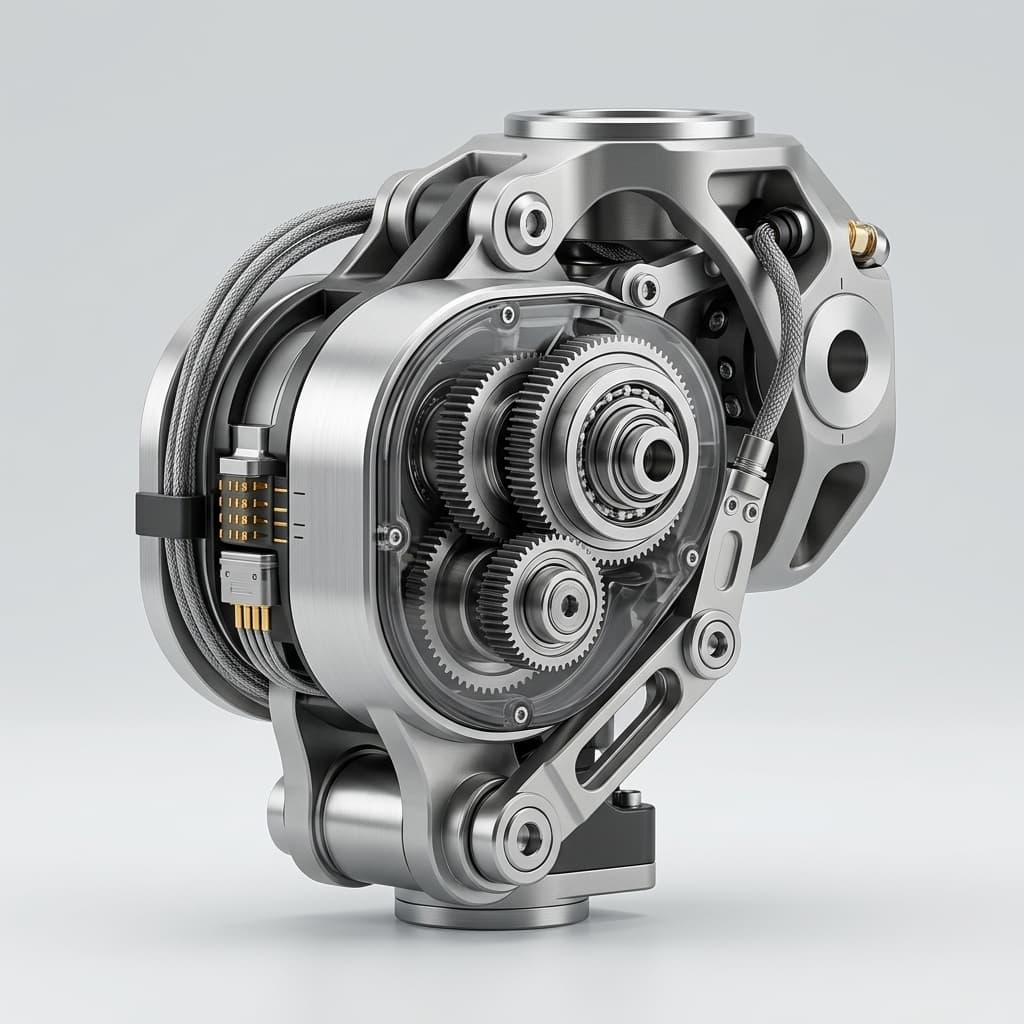
Humanoid Actuator Backlash Testing: RFQ Guide for Custom Reducers
How to evaluate reducer backlash claims for custom humanoid actuators, including preload, reversal method, assembled-joint testing, encoder location, and pilot-batch evidence.
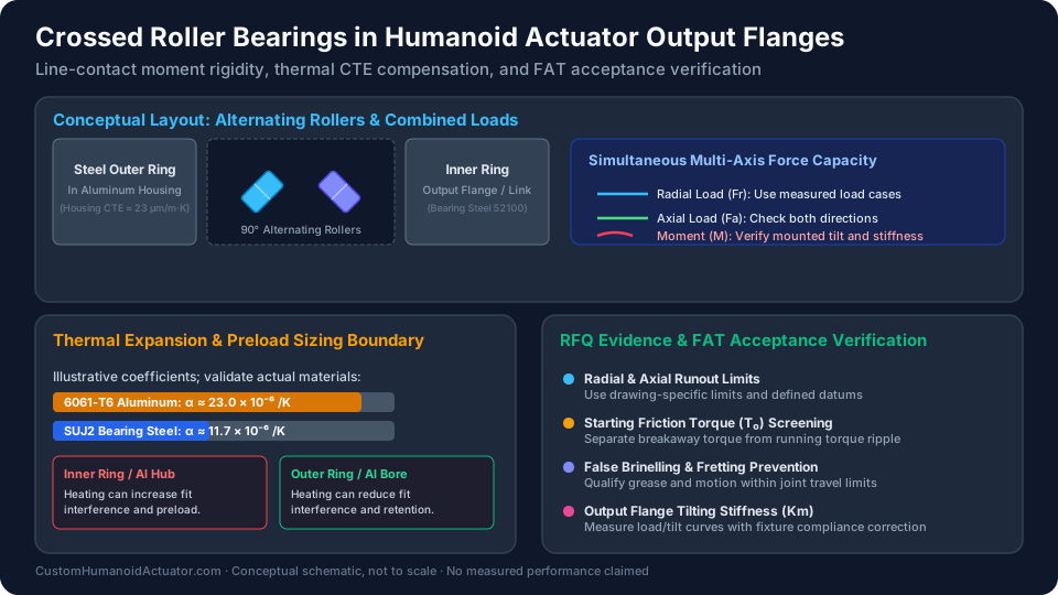
Crossed Roller Bearings in Custom Humanoid Actuators: Moment Rigidity, Preload Sizing, Dynamic Shock Tolerance, and Sourcing Acceptance Protocols
Compare crossed roller bearings for humanoid actuators: moment rigidity, thermal fits, shock loads, and supplier acceptance checks. Prepare your bearing RFQ.