
Four decisions before accepting continuous torque
- Match electrical definitions. Current and resistance conventions change calculated heating. Use the three-phase copper-loss basis before comparing suppliers.
- Specify the complete fixture. The thermal path is a property of the assembled test, including the mount. Motor heat-balance principles explain why a bare motor value does not settle a joint rating.
- Qualify each limiting component. The winding calculation leaves housing, grease, magnets and drive unverified. A grease laboratory result cannot substitute for dynamic reducer testing.
- Separate screening from acceptance. An estimate helps choose the test point. A rating needs an agreed physical test procedure and recorded limits; consult the applicable rating standard.
| Output | Use now | Still required |
|---|---|---|
| Average winding estimate | Screen torque, heat and ambient sensitivity | Calibrated fixture inputs and measured temperature |
| Winding-only torque ceiling | Identify a candidate load point | Reducer, drive, magnet and current limits |
| 95% rise time | Plan initial logging duration | Measured stabilization and observation window |
| Mechanical output power | Start rig power selection | Torque-speed envelope and overload checks |
Prepared by Custom Humanoid Actuator for joint design and sourcing teams. This is a planning guide; measured actuator qualification records must come from the actual test assembly.
Start with the actuator product families and use the sample RFQ package to record the installation boundary alongside the thermal inputs.
Model, equations and uncertainty
This page derives a steady-state, single-node model at constant output torque. It assumes a balanced star winding, sinusoidal line currents, a constant output Kt, constant fixture Rth and user-supplied other heat at this operating point. It ignores saturation, hot-magnet Kt changes and temperature dependence of non-copper losses. These assumptions must be checked before extrapolation. Thermal model background.
| Quantity | Equation | Meaning / boundary |
|---|---|---|
| Line current | I = T / Kt | Kt uses output Nm per line RMS ampere |
| Copper heat at 20°C | P20 = 1.5 I² RLL,20 | Derived from 3 I² Rphase for balanced star |
| Hot copper heat | Pcu(Tw) = P20 [1 + α(Tw − 20)] | α = 0.00393 /°C, approximate copper coefficient |
| Steady heat balance | Tw = Tamb + Rth [Pcu(Tw) + Pother] | All allocated heat acts on one average winding node |
| Closed-form temperature | Tw = {Tamb + Rth[P20(1 − 20α) + Pother]} / (1 − α P20 Rth) | Only finite when denominator > 0; beyond the entered limit is extrapolation |
| Winding-only torque ceiling | Tlim = Kt √{max[0, (Tmax − Tamb)/Rth − Pother] / [1.5 RLL,20 (1 + α(Tmax − 20))]} | Not a drive, mechanical or standstill hotspot rating |
| 95% rise time | t95 = −ln(0.05) τ ≈ 3τ | τ is a measured effective loaded value, not a bare winding constant |
No stable model equilibrium is reported when 1 − α P20 Rth ≤ 0. The mathematical critical torque is Kt / √(1.5 RLL,20 α Rth); it is a model boundary, not a component safety rating. Near this boundary, parameter error strongly amplifies the temperature prediction. The tool withholds non-finite outputs and asks you to lower load or revise cooling.
Vary measured inputs across their uncertainty bounds rather than relying on rounded single values. Recompute at higher ambient, resistance, other heat and Rth and at lower Kt. Where the margin disappears, collect better data or reduce the proposed load; the tool supplies no probabilistic confidence interval.
Electrical definitions that prevent false comparisons
| Supplier quantity | Required normalization | Consequence if unknown |
|---|---|---|
| Kt per peak sinusoidal line ampere | Kt_RMS = √2 × Kt_peak under that stated convention | Ask for line current and output torque at the test point |
| Phase winding resistance | RLL = 2 Rphase for star connection | Do not enter phase resistance as line-to-line resistance |
| Cold resistance at a known temperature | R20 = Rmeasured / [1 + α(Tmeasured − 20)] | Repeat four-wire measurement with temperature logged |
| Motor-only torque constant | Include reduction ratio and efficiency at the operating point | Obtain joint output calibration |
| DC bus current / dq current | Do not treat as line RMS without supplier conversion | Measure phase currents or confirm the drive scaling |
Torque reversals, varying reducer efficiency and magnetic saturation can make a single constant Kt inadequate. Log actual phase current and output torque during the physical test. The measurement example also shows why transient mechanical and electrical power must be synchronized.
Build a bench that measures the stated claim
Use the actual mounting interface, installation preload and thermal interface material. Guard the rotating shaft, align the coupling and check the weakest continuous and overload torque rating across the mechanical chain. For static holding, a reaction fixture can replace a rotating absorber, but it still needs load measurement and stable current control.
| Channel | Record | Qualification check |
|---|---|---|
| Output torque and speed | Synchronized time series; zero and drift checks | Calibration and range adequate at the actual low-speed point |
| Line current and voltage | Current convention, phase balance and drive settings | Capture relevant ripple; verify acquisition bandwidth for the drive |
| Winding temperature | Embedded sensor location or hot-resistance method | State sensor lag and average-versus-hotspot limitation |
| Reducer, housing, magnet/rotor and drive | Direct sensors or validated component-specific estimation | Compare each with the exact supplier limit |
| Ambient and mount | Air temperature, fixture drawing, cooling and contact details | Separate chamber air from local exhaust and fixture temperature |
Set a total uncertainty budget that resolves the smallest claimed thermal margin. Calibration class alone omits mounting, thermal gradients, drift, sampling and repeatability. Do not select a torque transducer or load motor from a fixed multiplier without checking overloads and the operating envelope.
Run a controlled continuous torque test
- Agree torque, speed, ambient, mount, drive configuration, winding and component limits, stop rules and the definition of stabilization. Select applicable clauses with the test lab; IEC 60034-1:2026 is a rating reference, not an automatic joint certificate.
- Check calibration and zero offsets. Measure cold winding resistance and temperature. Record assembly serial number, lubricant specification and firmware.
- Apply a lower commissioning load first. Confirm torque control, speed stability and plausible sensor response before increasing to the target point.
- Log synchronized torque, speed, current, ambient and all component temperatures. Stop on any agreed limit, sensor fault or unstable load condition.
- Evaluate measured temperature trend over the agreed observation window, with ambient stability and uncertainty accounted for. A brief flat reading is insufficient.
- After cooling, inspect and repeat at the required ambient, mounting and duty boundaries. Publish raw data, exclusions and the observed limiting component.
The tool reports a first-order 95% rise time only. If a lab chooses a slope criterion such as 1 K/h, document the source edition, calculation window, sensor resolution and ambient handling in its procedure. This page does not claim to have verified a mandatory clause number or universal dwell time.
Review this test scope with our engineering teamStandstill holding needs its own evidence
A humanoid knee holding a crouch can remain at nearly one electrical angle. Even if the ideal sum of phase current squares gives the same total copper heat as an equivalent rotating RMS case, individual phase temperatures can differ. A single-node average cannot locate the hottest slot or end turn.
Use standstill mode to force zero shaft power and review average heating. Then test several electrical angles under controlled holding torque, observe the hottest accessible winding locations, and agree a position-dependent limit where needed. A brake can reduce energized holding time but requires separate holding and release validation. The report makes no universal 19% or 29% stall derating claim.
Cooling choices: performance, cost and maintenance
| Option | Potential benefit / tradeoff | Minimum verification |
|---|---|---|
| Conductive limb mount | Uses existing structure; heat can spread to neighboring joints | Retest with real bracket, contact condition and nearby heat sources |
| Potting or impregnation | May improve an internal path; adds processing and repair difficulty | Check voids, stress and insulation compatibility; remeasure complete Rth |
| Forced air | May improve external convection; adds noise, fan power and contamination sensitivity | Test actual enclosure airflow and fan-failure behavior |
| Liquid cooling | Can move heat away from a dense joint cluster; adds pumps, seals and plumbing | Verify coolant boundary, leakage and loss-of-flow response |
| Reduce energized duty / use a holding brake | Can reduce average heat; changes motion and safety behavior | Test the actual cycle and brake load/release sequence |
Do not multiply the entire winding-to-ambient path by a guessed resin or fan factor. If only winding-to-housing resistance changes, the external path may still dominate. Compare alternatives at identical torque, speed and ambient and include the maintenance cost before selecting an option.
Three worked screening scenarios
These are synthetic demonstrations, not customer results or supplier performance data. Each uses 35 Nm, Kt 2.8 Nm/A RMS, terminal R20 0.45 Ω, 25 RPM, 5 W of assumed other heat, a 130°C winding limit and fitted τ of 30 min. Only the stated ambient or Rth changes. Results below are generated by the same model as the tool.
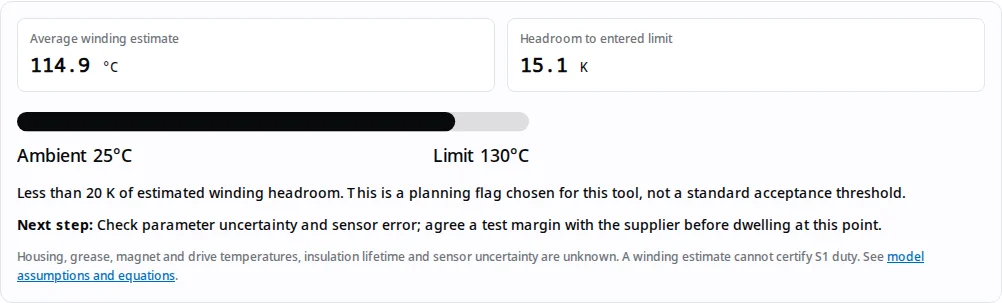
| Scenario | Ambient / fixture Rth | Average winding estimate | Total hot heat | Interpretation |
|---|---|---|---|---|
| 35 Nm example | 25°C / 0.6 K/W | 114.9°C | 149.8 W | Baseline screen: component limits and uncertainty still needed |
| Hot ambient example | 55°C / 0.6 K/W | 154.8°C | 166.3 W | Above winding limit: lower load or improve the measured thermal path |
| Lower Rth example | 25°C / 0.42 K/W | 82.2°C | 136.3 W | Lower estimate only if 0.42 K/W is measured in this fixture |
Scenario 1 — baseline: Enter the 35 Nm example and review current and hot copper heat. The predicted winding value supplies an initial test point, while the unknown reducer and drive temperatures prevent acceptance.
Scenario 2 — hot ambient: Keep the same load and thermal path, raise ambient from 25°C to 55°C and recalculate. Copper feedback raises the final winding temperature by more than the ambient change. Reduce load before a hot-chamber dwell.
Scenario 3 — changed fixture: Keep 25°C ambient but enter Rth 0.42 K/W. The estimate falls; this is a sensitivity study. Measure that resistance in the real limb before crediting any cooling benefit.
Unknowns that can change the decision
| Risk | Effect on the decision | Mitigation / alternative |
|---|---|---|
| Wrong current or resistance definition | Large heat error before thermal calculations begin | Normalize supplier inputs or measure torque/current and terminal resistance |
| Unmeasured Rth or omitted other heat | False apparent headroom | Treat output as a sensitivity study; fit an instrumented assembly model |
| Long hold or slow motion | Average heat misses local phase hotspots | Test fixed angles; use a multi-node model if sensors are insufficient |
| Grease, magnets, electronics or touch surfaces | Joint can exceed a component limit below winding Tmax | Unknown until measured; obtain exact component limits |
| Overbuilt rig or cooling solution | Unnecessary sensor, load motor and maintenance cost | Set uncertainty and operating envelope first; compare quotes on the same test scope |
| Changed mount, enclosure, drive or duty | Original evidence may no longer represent installation | Retest the changed boundary or restrict the claim to the tested one |
ASTM D6184-22 is useful for a specified lubricant laboratory test, but its results do not predict dynamic-service oil separation. A fixed grease temperature knee or an actuator MTBF cannot be inferred here. ASTM scope and limitations.
System safety and accessible-surface limits require application-specific review. ISO 10218-1:2025 addresses industrial robots within its scope; it does not make this component calculator a humanoid safety assessment.
Record what was actually qualified
| Phase | Record | Decision supported |
|---|---|---|
| Engineering prototype | Fixture model, electrical definitions, thermal sweep and sensor placement | Choose candidate operating points and identify missing data |
| Design validation | Repeat at installation boundaries with component limits and uncertainty | Freeze the rating for the specified assembly and conditions |
| Production validation | Repeat across agreed lots, tolerances and assembly processes | Set acceptance controls; sample count follows risk and variation |
| Installation or design change | Compare revised mount, drive, lubricant or enclosure with baseline | Retain, restrict or requalify the original continuous torque claim |
Include failures, interrupted tests and excluded samples. Report the limiting component even when winding temperature is acceptable. Avoid extending a short hot dwell into a lifetime claim; endurance testing is a separate evidence stream.
Minimum supplier evidence checklist
- Torque-speed point, peak duration, duty cycle and output current definition.
- Assembly serial numbers, reducer and lubricant specification, drive settings and firmware.
- Mounting drawing, preload, thermal interfaces, ambient and any active cooling.
- Raw synchronized torque, speed, phase current and temperature logs, including warm-up and cool-down.
- Calibration records, sensor locations, uncertainty, stabilization rule and all component stop limits.
- Observed limiting component, repeatability, failed runs and the conditions under which the claim stops applying.
If fixture Rth, current convention or component limits are missing, send the checklist and request an instrumented pilot test before accepting a continuous rating. Compare compliance evidence and backlash test conditions as separate qualification dimensions.
Organize the recorded logs with the actuator evidence library and return to the engineering resources for the wider sample qualification workflow.
Engineering and sourcing FAQ
Electrical inputs
Which current convention does the calculator use?
Motor line RMS amperes under balanced sinusoidal commutation. Kt must be output torque divided by that current, including the reducer at the operating point. A drive DC bus current or a peak-current Kt cannot be entered directly.
How do I convert a peak-current torque constant?
If the supplier defines torque as Kt_peak times the amplitude of a sinusoidal line current, Kt_RMS equals sqrt(2) times Kt_peak. Confirm the exact convention with the supplier; a dq current definition can use a different scaling.
Why is the copper-loss factor 1.5?
For a balanced star winding, terminal line-to-line resistance is twice one phase resistance. Three equal phase RMS currents give Pcu = 3 I² Rphase = 1.5 I² RLL. This calculator excludes delta windings and other commutation conventions.
Can I enter a resistance measured at room temperature?
Convert it to 20°C first: R20 = Rmeasured / [1 + 0.00393 (Tmeasured − 20)]. Measure winding temperature with resistance, compensate lead resistance, and document uncertainty.
Is mechanical output power part of the heat budget?
No. Shaft power is torque times angular speed and leaves the actuator mechanically. The thermal budget here compares hot copper heat plus the other heat allocated by the user; it does not compare shaft power.
Thermal boundaries
Does selecting standstill automatically derate torque?
No. Standstill fixes speed to zero and shows only an equivalent average copper-heating estimate. Actual phase hotspots depend on electrical angle, geometry and cooling; instrument multiple rotor angles before accepting a holding rating.
Can I use the motor catalog thermal resistance?
Only if it represents the same complete winding-to-ambient path and mounting condition. A bare winding-to-housing value is incomplete. Measure the assembled actuator in its limb bracket or document the missing external path.
Does potting guarantee a fixed temperature reduction?
No. Resin conductivity, contact area, impregnation quality, voids and external cooling interact. Measure the complete thermal path after the change; this tool applies no automatic potting credit.
Does a winding estimate also predict grease temperature?
No. Reducer losses and thermal paths need separate sensors or a validated multi-node model. Housing, grease, magnet and drive temperatures remain unknown in this tool.
Does a 10 K temperature change predict insulation lifetime?
A general aging rule cannot establish actuator life or MTBF. Insulation-system endurance data, stress profile and other failure modes are required. This page provides no lifespan multiplier or service-life guarantee.
Test execution
Is three time constants a pass criterion?
No. A fitted first-order model reaches about 95% of its final rise at three time constants. Establish the actual stabilization slope, observation window and all component limits in the agreed test procedure.
What does no stable model equilibrium mean?
The copper-feedback denominator is zero or negative, so this linear model has no finite steady-state solution. Reduce current or thermal resistance. The calculator withholds temperature and dwell outputs rather than interpreting infinity as a physical temperature.
How should the load motor be selected?
Check the operating torque-speed envelope, continuous mechanical power, low-speed torque control, overload torque, coupling limits and thermal rating. The calculated shaft watts alone are insufficient for rig selection, especially near zero speed.
What sensor accuracy class is mandatory?
There is no universal class specified by this page. Set the total allowed measurement uncertainty relative to the smallest claimed margin, then include calibration, drift, mounting and acquisition errors for the complete measurement chain.
Does ASTM D6184 define a reducer grease limit?
No. It is an oil-separation laboratory test, and ASTM excludes predicting dynamic-service separation from its results. Use the exact lubricant and reducer supplier limits and measure the actual test assembly.
Supplier decisions
Can a supplier quote continuous torque as a fraction of peak?
A fraction alone does not establish a rating. Request torque, speed, ambient, mounting, thermal logs and limiting component for the tested operating point. Peak duration and recovery conditions should be specified separately.
What happens when I leave optional fields blank?
The winding estimate remains available. Heat-budget usage and the continuous-to-peak ratio are marked not specified. Required fields must contain finite numbers inside the stated ranges.
What if clipboard access is blocked?
Open the current test-plan text beneath the copy button, select it and copy manually. The text includes assumptions, unavailable outputs and next steps; no data is sent automatically.
Can repeated motion be reduced to RMS torque?
RMS torque is a first screen when torque is proportional to current and cycle time is short relative to the relevant thermal dynamics. Long holds, varying efficiency, different speeds and load reversals require time-resolved current and temperature testing.
What is the minimum useful supplier evidence package?
Ask for the actual fixture drawing, electrical definitions, time-series torque/speed/current and temperature logs, sensor calibration, agreed limit criteria and the observed limiting component. Retest when the mount, drive or cooling changes.
Discuss your actuator torque test plan
Bring the estimator summary and the evidence checklist to the engineering discussion. Identify assumed inputs before agreeing a test scope.
Inquiry Email
Include target torque/speed, quantity, and delivery location.
Application Engineer
+8618857971991
Talk directly about drawings, torque-speed targets, and RFQ data gaps.
Sources, editions and limits of the evidence
Public publisher pages and the engineering references below were checked on . Full licensed standards clauses were not independently audited. Equations and scenario outputs are our stated model derivations; they are not published actuator measurements. Recheck applicable editions when writing a test contract.
- Teledyne LeCroy — Dynamic Rapid Motor Acceleration Loss Measurements (2017)
Supports: Three-phase electrical and shaft measurements; copper-loss calculation using 3 × phase RMS current squared × phase resistance.
Limit: The calculator derives its 1.5 × I² × RLL form for a balanced star winding. The article does not validate our example actuator or fixture.
- Portescap — Thermal Considerations for Ironless Brush DC and Brushless DC Motors (2021)
Supports: Motor heat balance, temperature-dependent copper resistance, and separate internal and external thermal paths.
Limit: A motor thermal explanation is not a calibrated model for a geared joint. This page derives a single-node screening model; its inputs require measurement.
- IEC 60034-1:2026 RLV — Rotating electrical machines: Rating and performance
Supports: Current rating/performance reference; the 2026 edition replaces the 2022 edition.
Limit: Public catalog scope only was checked. Agree the applicable clauses and full licensed test procedure with the test laboratory. This tool does not establish IEC conformity.
- ASTM D6184-22 — Oil Separation from Lubricating Grease (Conical Sieve Method)
Supports: A laboratory method for evaluating oil separation at elevated temperature for specifications and quality control.
Limit: ASTM expressly excludes predicting oil separation under dynamic service. It provides no universal 75–80°C reducer operating threshold.
- ISO 10218-1:2025 — Robotics: Safety requirements, Part 1: Industrial robots
Supports: Published industrial-robot safety standard, edition 3, February 2025.
Limit: Applicability to a particular humanoid system requires a scope review. A component thermal estimate is not robot safety certification or a universal touch-temperature limit.