
Custom Humanoid Actuator Compliance Testing
Estimate loaded joint deflection, then plan the measurements and safety evidence your actuator RFQ needs.
Published · Reviewed · By Custom Humanoid Actuator
Discuss your compliance test planDeflection calculator
Default example shown. Enable JavaScript to edit inputs.
Illustrative inputs. Elasticity estimate only; no human contact safety certification. All inputs required except the budget.
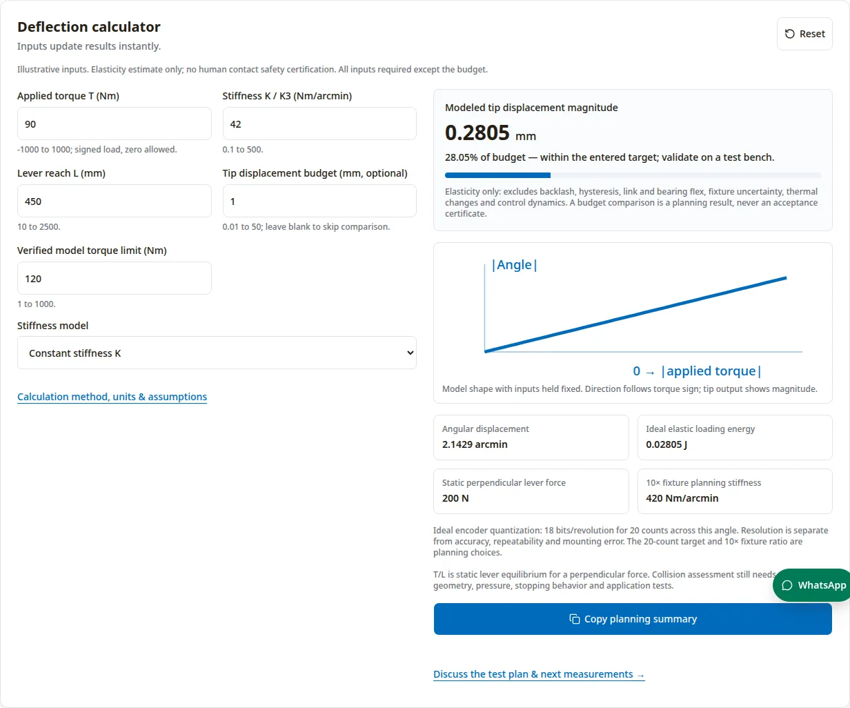
Elastic tip estimate: 0.2805 mm
-1000 to 1000; signed load, zero allowed.
0.1 to 500.
10 to 2500.
0.01 to 50; leave blank to skip comparison.
1 to 1000.
Modeled tip displacement magnitude
0.2805 mm
28.05% of budget — within the entered target; validate on a test bench.
Elasticity only: excludes backlash, hysteresis, link and bearing flex, fixture uncertainty, thermal changes and control dynamics. A budget comparison is a planning result, never an acceptance certificate.
- Angular displacement
- 2.1429 arcmin
- Ideal elastic loading energy
- 0.02805 J
- Static perpendicular lever force
- 200 N
- 10× fixture planning stiffness
- 420 Nm/arcmin
Ideal encoder quantization: 18 bits/revolution for 20 counts across this angle. Resolution is separate from accuracy, repeatability and mounting error. The 20-count target and 10× fixture ratio are planning choices.
T/L is static lever equilibrium for a perpendicular force. Collision assessment still needs mass, speed, geometry, pressure, stopping behavior and application tests.
Discuss the test plan & next measurements →Five decisions before approving a test plan
Use the calculator to size an elastic error contribution. Use the following evidence checks to decide what still needs measurement. Numerical examples and planning ratios below are editorial calculations, not factory test results.
Separate elasticity from reversal error. A loading stiffness cannot replace a measured hysteresis curve.
Keep measured transition torques fixed. The manufacturer three-zone method uses model-specific slopes and breakpoints.
Allocate fixture error before comparing suppliers. The series-spring derivation quantifies the error introduced by an uncorrected bench.
Choose standards by intended use. Industrial robot and personal care robot scopes differ.
Keep drive safety evidence separate from mechanical acceptance. Drive functional safety needs integration and validation evidence.
Method, units and operating boundaries
The tool treats a joint as a reversible torsional spring and a limb as a rigid lever. It uses a loading model in either direction, with no preload offset. The three-zone option assumes the same curve for positive and negative torque. Use measured directional curves when that symmetry is untrue.
Notation: theta is angular displacement; theta_rad is the same angle in radians; d is endpoint displacement; pi is the circle constant; dT is a torque increment. Sum means add the active segment contributions.
| Output | Calculation | Boundary |
|---|---|---|
| Angle, constant K | theta = T / K in arcmin; theta_rad = theta × pi / 10800 | K must describe the same torque range and assembly. |
| Three-zone angle magnitude | sum dT / Ki across the active loading segments | Transitions satisfy 0 < T1 < T2 ≤ verified model limit. |
| Tip displacement magnitude | d = 2L sin(|theta_rad| / 2) | Single rigid lever endpoint displacement, not full robot pose error. |
| Recoverable loading energy | U = sum (Tb² − Ta²) / (2Ki) × pi / 10800 | Ideal elastic loading only; excludes hysteresis losses and impact dynamics. |
| Static lever force | |T| / (L / 1000) in N | Perpendicular equilibrium force; no collision prediction. |
| Stiffness conversion | 1 Nm/arcmin = 3437.74677 Nm/rad | A unit mismatch changes the result by orders of magnitude. |
Tool input limits are interface limits, not approved operating ratings: torque −1000 to 1000 Nm; verified model torque limit 1 to 1000 Nm; each stiffness 0.1 to 500 Nm/arcmin; lever 10 to 2500 mm; optional budget 0.01 to 50 mm. Results stop above the entered model torque limit or 10° modeled rotation. Zero torque is valid. For a rotating multi-joint mechanism, combine measured joint errors with the actual kinematic Jacobian and structural deformation.
Budget labels compare only the entered elastic displacement: “near” means over 80% through 100%, and “exceeds” means over 100%. This 80% warning is an interface planning choice, not a standard. No result asserts robot safety or product acceptance.
Loading stiffness and hysteresis need different evidence
Harmonic Drive documents a three-line approximation to a nonlinear loading curve. That is a product-specific model, not a universal JIS-defined stiffness ratio. Obtain K1, K2, K3, T1 and T2 for the exact reducer and assembly. Do not infer them from architecture names.
For |T| ≤ T1, angle magnitude is |T|/K1. Between T1 and T2 it is T1/K1 + (|T|−T1)/K2. Above T2 it is T1/K1 + (T2−T1)/K2 + (|T|−T2)/K3. The summed form stays continuous at both transitions. In a linear model, U = T × theta_rad / 2; in a nonlinear model the tool instead integrates each segment.
Record the unloading and negative-loading paths to characterize reversal behavior. State the torque window used for any lost-motion metric. A supplier's “zero backlash” description does not prove zero lost motion, zero elastic windup or zero assembled-joint error. See the manufacturer discussion of hysteresis and component boundaries.
Architecture tradeoffs: what to ask, not what to assume
This qualitative sourcing comparison identifies questions for a design review. It supplies no universal bandwidth, reflected-inertia, shock multiplier or stiffness rating; those depend on the selected assembly and controller.
| Architecture | Potential design advantage | Evidence needed / cost tradeoff |
|---|---|---|
| Strain-wave reducer | Compact high-ratio joint; nonlinear loading behavior can be modeled. | Measure low-load reversal, temperature and peak-load limits. A component catalog curve omits housing and output interface flex. |
| Low-ratio / QDD | Low ratio can aid backdrivability and active impedance design. | Measure actual backdrive friction, reflected inertia and current-to-output torque behavior. Controller dependence adds validation effort. |
| Series elastic actuator | An intentional spring enables elastic deflection sensing. | Characterize the complete spring/transmission assembly and resonance. Extra travel and sensors may add packaging and calibration cost. |
| Cycloidal reducer | Candidate for compact load transmission with multiple contacts. | Verify measured stiffness, lost motion, friction and bearing tilt. Do not substitute an assumed shock multiplier for endurance tests. |
Bench design and fixture uncertainty
For an ideal actuator spring Ka and fixture spring Kf in series, theta_measured = T/Ka + T/Kf. Therefore Kmeasured = KaKf/(Ka+Kf). The two percentages below use different denominators; stating only “fixture error” is ambiguous.
| Fixture ratio Kf/Ka | Added angle / actuator angle | Measured stiffness below Ka |
|---|---|---|
| 3× | 33.33% | 25.00% |
| 10× | 10.00% | 9.09% |
| 20× | 5.00% | 4.76% |
| 100× | 1.00% | 0.99% |
The calculator's 10× target is an initial fixture-sizing aid. For tighter measurement uncertainty, characterize and subtract fixture twist, improve stiffness or redesign the measurement reference. Two encoders and a high bit count do not automatically correct mounting compliance.
| Element | Record / control | Reason |
|---|---|---|
| Torque measurement | Calibration range, uncertainty, alignment and load direction | A transducer class label alone is not a complete uncertainty budget. |
| Angle measurement | Angular accuracy, resolution, mounting eccentricity and reference locations | The tool’s 20-count quantization target is only a sizing choice. |
| Input lock and fixture | Residual motion under load and independent correction | Avoid attributing fixture deformation to the joint. |
| Temperature | Ambient, motor and housing temperatures plus stabilization condition | Compare suppliers under the same thermal boundary. |
| Load history | Sweep rate, dwell, preload cycles and direction | Reversal and friction can depend on test history. |
| Assembly | Serial, firmware, lubricant, fastener torque and bearing setup | A reducer component and an assembled joint have different boundaries. |
Build the torque-angle record and acceptance checklist before asking a lab for a quote.
Prepare your actuator RFQ packageA practical qualification sequence
This sequence is a proposed engineering workflow. Agree sample counts, sweep range, thermal conditions, shock profiles and acceptance limits from the actual mission and failure risks; no universal humanoid DVT recipe is asserted.
- Freeze the test boundary. Identify whether the deliverable covers a reducer, integrated actuator or complete joint with mounting structure.
- Calibrate the chain. Verify force/torque and angle channels, input restraint, alignment and fixture correction at the planned loads.
- Record reversible loading. Use an agreed safe bidirectional torque sweep, with raw time, torque, angle and temperature records. Define rate, dwell and conditioning before comparing curves.
- Repeat relevant operating conditions. Include cold/hot states and load histories selected from intended use. Check the test unit is within its approved limits.
- Assess mission-specific durability separately. Derive impact and endurance tests from load cases. Retest stiffness, reversal and visible damage afterward; do not equate stored spring energy to a certified drop rating.
- Review acceptance with uncertainty. Agree the decision rule, nonconformance handling and production screening before purchase. Track design changes that invalidate earlier evidence.
Standards map: start with intended application
Publisher records checked on . These public scopes help assign an owner for the next review. Detailed clauses, national adoptions and applicable legal requirements still need project-specific confirmation.
| Reference | Publicly stated scope | Next review |
|---|---|---|
| ISO 10218-1:2025 | Industrial robot safety. | Robot manufacturer: verify design and intended-use requirements. |
| ISO 10218-2:2025 | Industrial robot applications and cells. | Integrator: assess the complete task, tooling and work environment. |
| ISO/TS 15066:2016 | Collaborative industrial robot systems; remains listed as published with revision work. | Safety reviewer: confirm relation to adopted ISO 10218 editions and contact test conditions. |
| ISO 13482:2014 | Personal care robot categories; replacement anticipated in the publisher listing. | Application owner: confirm category, exclusions and current edition. |
| ISO 13849-1:2023 | Safety-related control system design methodology. | Safety engineer: select required functions and performance using applicable risk assessment. |
| IEC 61800-5-2:2016 | Safety-related power drive systems. | Drive and integration teams: validate subsystem and application behavior. |
Removing drive torque does not by itself validate braking, load holding or a safe fall response. A gravity-loaded limb needs a defined safe state and verified transition behavior. Avoid universal claims such as “STO within 10 ms makes contact safe” or “all joints require PLd Category 3.”
For EU deployment planning, the European Commission machinery guidance gives 20 January 2027 as the general application date, with some provisions earlier. Determine the relevant product category and placing-on-market date. Check current regional standards and legal status separately from an ISO publication date.
Misuse, cost and application mismatch risks
| Risk | Consequence | Minimum action / alternative |
|---|---|---|
| Treating T/L as collision safety | Ignores dynamic impact and contact pressure. | Use a qualified application-level assessment and instrumented contact testing. |
| Sizing from a single K3 value | May underestimate displacement at lower loads. | Obtain the loading curve and use applicable slope segments. |
| Ignoring fixture uncertainty | Supplier comparisons can reverse after correction. | Specify references and uncertainty; use a calibrated fixture or a revised rig. |
| Over-specifying every unit test | Unnecessary equipment, test time and destructive sample costs. | Separate design qualification from production screening using a risk-based plan. |
| Transferring industrial criteria to personal care | The selected standards may not match the product. | Confirm intended use and scope before commissioning a lab. |
| Extrapolating cold static data to walking impacts | Misses rate effects, heating and structural resonance. | Add mission-specific thermal/dynamic tests; use static results only within their measured scope. |
Four worked planning examples
These are synthetic, reproducible cases using the equations above. They are not measured products, case studies or safety test results. Keep torque in Nm, stiffness in Nm/arcmin and lever in mm.
| Case and assumptions | Modeled result | Decision / next measurement |
|---|---|---|
| A: linear joint; T=90, K=42, L=450; budget=1 mm; model limit=120 Nm | theta=2.1429 arcmin; d≈0.28050 mm; budget use≈28.05% | Elastic allocation is below target. Measure reversal, fixture and link contributions before accepting the assembly. |
| B: same joint with K1=21, K2=35, K3=42; T1=20, T2=50 Nm | theta=2.7619 arcmin; d≈0.36153 mm; about 29% above case A | A single high-load slope understates this example. Fit all segments from measured data. |
| C: more compliant illustration; T=60, K=8.5, L=400; budget=0.5 mm; model limit=120 Nm | theta=7.0588 arcmin; d≈0.82133 mm; budget use≈164.27% | Exceeds allocation. Verify units, then revise load, geometry or stiffness; report the full over-budget percentage. |
| D: unloaded joint; T=0, K=42, L=450; no budget | Angle, displacement and ideal energy=0; encoder sizing undefined | Zero load is no evidence of loaded accuracy. Test a nonzero load within the verified model range. |
Ankle or knee under load
Use cases A/B to compare modeling assumptions. Add real bearing tilt, link geometry and ground-load conditions before assigning the balance error budget.
Assembly arm or compliant wrist
Use case C to screen the elastic allocation. Insertion success also depends on friction, sensing and the controller; a stiffness calculation alone cannot predict it.
Turn estimates into an acceptance evidence package
| Decision | Known from this page | Unknown until supplied or measured |
|---|---|---|
| Elastic sizing | Deterministic equations and example inputs. | Exact assembly slopes, directional asymmetry and temperature dependence. |
| Bench capability | Series-spring relationship and quantization estimate. | Calibrated accuracy, total uncertainty and fixture correction. |
| Production consistency | A list of traceability fields to request. | Batch distributions, drift and agreed production sample plan. |
| Safety or conformity | Publisher scope records and review date. | Application hazards, adopted requirements, validation results and declarations. |
Request raw torque-angle CSV files with units, time base, direction, temperature and specimen identity; a plot showing both loading directions; calibration records; fixture correction; and versioned acceptance limits with a decision rule for uncertainty. Keep destructive mission testing separate from the production screen. No batch data, universal thermal drift percentage or guaranteed qualification service is claimed here.
Frequently asked engineering and sourcing questions
Model and inputs
Does compliance mean elasticity or regulatory conformity?
Both meanings occur in actuator sourcing. The calculator addresses elastic joint deformation. The standards map helps scope a separate robot and application safety review. Neither output is a certificate.
What units should I enter for stiffness?
Enter Nm per arcminute. To convert a supplier value in Nm/rad, divide by 3437.74677. For example, 144385 Nm/rad is approximately 42 Nm/arcmin. Do not enter Nm/degree without conversion.
Can I test zero or negative torque?
Yes. Zero gives zero modeled angle, displacement and elastic energy; an encoder bit target is undefined at zero. Negative torque reverses angle under the symmetric loading assumption, while displacement magnitude and energy stay nonnegative.
Why are T1 and T2 separate from applied torque?
They locate fixed transitions on a measured loading curve. Scaling transitions with every new applied load changes the material model and prevents a meaningful comparison between test points. Keep them fixed unless you have a different measured curve.
Bench testing and uncertainty
Can the tool calculate hysteresis loss?
No. It computes a constant-stiffness or three-zone loading estimate. Hysteresis needs measured loading and unloading paths. Integrate the measured closed torque-angle loop to assess dissipated energy, using radians for angle.
Is a 10× stiffer fixture sufficient?
It is a planning choice. In the ideal two-spring model, a 10× fixture makes measured stiffness 9.09% lower than actuator stiffness. Fixture angle contributes 10% of actuator angle. Calibrate or correct the fixture for tighter uncertainty.
Do two encoders eliminate fixture error?
No. Their placement defines the included measurement chain. Verify mounting movement, bearing seats, couplings and input-lock motion separately. Encoder resolution alone says nothing about total angular accuracy.
What if the supplier gives only one stiffness number?
Ask for units, torque range, loading direction, temperature, mounting boundary and raw torque-angle records. Use a constant stiffness estimate only within the conditions represented by that number. Request more evidence for low-torque reversal behavior.
Safety and standards
Which ISO 10218 edition is referenced here?
The publisher lists ISO 10218-1:2025 and ISO 10218-2:2025. Check the referenced publisher records, adopted regional editions and project requirements before selecting a compliance plan.
Can T/L predict a safe collision force?
No. It is a static equilibrium estimate for force perpendicular to a lever. Collision assessment additionally depends on mass, speed, contact geometry, pressure, constraints and stopping behavior. No human-contact safety status is generated here.
Does Safe Torque Off ensure a humanoid limb stops safely?
A torque-off command does not establish controlled deceleration, isolation from every energy source or load holding. A gravity-loaded limb can move when torque is removed. Validate stopping and holding behavior, including brakes where required, in the complete application.
Does the EU Machinery Regulation already apply in full?
The European Commission gives 20 January 2027 as its general application date, with certain provisions applying earlier. The page was reviewed on 22 October 2026. Confirm the relevant legislation for the product and its placing-on-market date.
Sourcing and next steps
Are the example values measured CHA product specifications?
No. All calculator defaults and worked cases are numerical illustrations. There is no public batch qualification dataset on this page. Replace them with supplier evidence for the exact serial number, configuration and test conditions.
How many DVT samples should I specify?
Choose sample count from failure severity, design variation, destructive test needs and required confidence. This page does not impose a universal sample size. Define both design-qualification sampling and production controls in the purchase agreement.
What should I do when the budget is exceeded?
Check units and fixture correction first. Then consider a stiffer measured assembly, a shorter lever, reduced load or a revised error allocation. Repeat the calculation and validate the selected option at the actual operating conditions.
What should an actuator compliance RFQ include?
Provide torque envelope, lever geometry, displacement budget, temperature, mounting, load history and intended application. Request versioned raw measurements, calibration evidence, uncertainty, acceptance criteria and an explanation of which assembly elements the test includes.
Discuss your actuator compliance test plan
Bring the calculator summary and your measured data. Identify gaps in the proposed test scope, assembly boundary and acceptance criteria with the engineering team before commissioning tests.
Include joint location, torque envelope, lever geometry, displacement allocation, mounting, temperature, load history, quantity and intended use. Identify the safety review owner and any applicable standards separately.
Inquiry Email
Include target torque/speed, quantity, and delivery location.
Application Engineer
+8618857971991
Talk directly about drawings, torque-speed targets, and RFQ data gaps.
Sources, scope and review date
Public publisher records accessed on . These sources establish terminology and scope; they do not validate the example numbers or provide product test evidence. Recheck editions and applicability before a design freeze. The calculator equations, fixture comparison and worked examples are explicit mathematical derivations.
Maintained by Custom Humanoid Actuator. Review every six months, or sooner when a cited standard changes; next scheduled review: 22 April 2027. Send corrections with the source revision through the inquiry form.
- Harmonic Drive — CSF/CSG catalog, rev. 20161027, pp. 50–51 (opens in a new tab)
Manufacturer description of load-dependent stiffness with K1, K2, K3 and transition torques T1, T2.
Evidence boundary: Product-family documentation, not a universal test standard. It does not establish the example inputs on this page or certify a custom joint.
- Harmonic Drive — CSF/CSG catalog, rev. 20161027, p. 51: hysteresis (opens in a new tab)
Describes input-locked bidirectional torque loading for hysteresis measurement; the preceding page defines the loading stiffness segments.
Evidence boundary: Confirm the actual model, revision, units and assembly boundary. An assembled actuator includes additional elastic elements.
- ISO 10218-1:2025 — Industrial robots (opens in a new tab)
Published 2025 edition covering industrial robot safety before application integration.
Evidence boundary: Public scope verified; detailed normative clauses require the licensed standard. A joint calculator cannot establish conformity.
- ISO 10218-2:2025 — Industrial robot applications and robot cells (opens in a new tab)
Covers industrial application integration and lifecycle safety.
Evidence boundary: Check intended use and exclusions. This is not a blanket standard for every public-facing humanoid.
- ISO/TS 15066:2016 — Collaborative robots (opens in a new tab)
Published specification for collaborative industrial robot systems and their work environment.
Evidence boundary: The ISO listing remains published and identifies a revision project. Confirm its relationship with the adopted ISO 10218 editions; no numerical contact table is reproduced here.
- ISO 13482:2014 — Personal care robots (opens in a new tab)
Scope includes mobile servant, physical assistant and person carrier robots, with exclusions including medical and industrial robots.
Evidence boundary: The listing anticipates a replacement. Recheck the applicable edition before procurement; its public abstract highlights gaps in exhaustive collision injury data.
- ISO 13849-1:2023 — Safety-related parts of control systems (opens in a new tab)
Methodology for design and integration of control-system safety functions.
Evidence boundary: Its scope explicitly does not select the functions or required performance levels for a particular application.
- IEC 61800-5-2:2016 — Drive functional safety (opens in a new tab)
Design, integration and validation framework for safety-related power drive systems.
Evidence boundary: Drive subsystem evidence is only part of application safety. The listing shows an amendment under development; recheck before design freeze.
- European Commission — Machinery Directive and Regulation (EU) 2023/1230 (opens in a new tab)
The general application date is 20 January 2027, with some provisions applying earlier.
Evidence boundary: Determine product classification, placing-on-market date and applicable legislation separately. Publication of an ISO standard does not by itself make every clause a legal duty for all robots.