
Custom Humanoid Actuator Contract Manufacturing
Prepare an RFQ, assign production owners and define acceptance evidence.
Request a manufacturing scope reviewInteractive RFQ planner
Scope your manufacturing RFQ
Set a batch to see workcells and delivery gates.
1–1,000,000 whole units per order. Default: 150; illustrative knee pilot.
9 workcellsto verify with suppliers
7 deliverablesto agree before release
Planning rules only. Price, lead time, supplier equipment and certifications need confirmation. Safe speed, torque gain and yield require design-specific test evidence.
Review and copy your RFQ brief ↓Manufacturing scope (all fields required; defaults shown)
Selections describe proposals for review. They do not establish certification, suitability or an agreed test profile.
Optional quote arithmetic (USD)
Enter supplier quote values or your own scenario. Blank means unknown; zero means explicitly zero. Presets clear these amounts.
0–1,000,000,000 USD; at most two decimals. The page supplies no market price assumptions.
Quote scenario
Awaiting both quote inputs
Batch subtotal = quantity × entered unit price + entered NRE.
Excludes freight, duties, taxes, validation and spares unless included in your quote. Lead time remains unconfirmed.
Workcells to verify
- Housing machining and dimensional inspection
- Stator winding and insulation verification
- Rotor retention and balance verification
- Reducer / transmission assembly and lubrication control
- Encoder alignment and firmware configuration
- Serialized end-of-line inspection
- Load fixture and application-specific impact validation
- Resin dispensing, cure control and void inspection
- Component particle inspection and tailored environmental screening
Delivery gates to agree
- Revision-controlled drawing, BOM and approved supplier list
- Measurement-system calibration and agreed acceptance limits
- Serial-linked test records, deviations and rework history
- Signed DFM responsibility and design-change approval matrix
- System safety-function requirements and component evidence requested by the integrator
- Agreed extraction method, particle limits and screening profile; limits remain to be specified
- PVT exit: measured first-pass yield, process capability and repeatable station instructions
DFM questions and limits
- Freeze datums, airgap stackup and hot / loaded deflection limits on released drawings.
- Agree lubricant, fill quantity and inspection method with the transmission supplier.
- Rotor speed, thermal torque gain and line yield require design data and measured validation; this tool cannot predict them.
- Validate resin compatibility, cure shrinkage and thermal response on the actual winding / housing assembly.
- Verify sleeve interference, added magnetic gap, thermal expansion and overspeed containment with the rotor designer.
Decisions before supplier award
A planning framework with explicit evidence boundaries.
Define acceptance before tooling
Release drawings, inspection methods and change authority before committing to dedicated fixtures.
Editorial ownership frameworkSpecify the component, not just the room
Air classification and component particles require separate acceptance evidence.
ISO 16232 / ISO 14644-1 scopeTailor validation to the application
Workmanship acceptance and environmental testing need separately approved plans.
IPC / DLA source scopeNormalize quote scope and unknowns
Use supplier-entered amounts for arithmetic. Confirm MOQ, lead time and qualification separately.
Disclosed arithmetic methodPublic sources below establish method scope. Workcell routes, ownership allocations and checklists are editorial planning guidance. Supplier capabilities, prices, measured performance and customer outcomes are not verified here.
1. Map workcells and subcontractor responsibility
Buy a controlled process route with named owners, inspection handoffs and release records. A list of machine brands alone cannot demonstrate repeatability.
Basis: Editorial sourcing method: follow the part from incoming material through housing machining, winding, rotor assembly, transmission integration, calibration and final inspection. Ask for a redacted traveler from a comparable part.
Limits and unknowns: In-house equipment and approved subcontracting are both possible. This page contains no verified factory equipment inventory or capacity audit.
Next step: Mark every station as in-house, subcontracted or unconfirmed; identify who accepts nonconforming material at each handoff.
2. Choose a contract manufacturing ownership model
Use build to print for a released design, co-engineering for unresolved DFM work, or platform adaptation when an existing module fits the interface and duty cycle.
Basis: Editorial comparison: design authority, change rights, tooling ownership and access to test data determine the practical boundary of each engagement.
| Decision | Build to print | Co-engineering | Platform adaptation |
|---|---|---|---|
| Design authority | Customer releases drawings | Name the owner for each interface | Supplier owns platform; customer approves fit |
| BOM and substitutions | Customer-controlled AVL | Joint selection with approval rules | Request change notice and critical-item disclosure |
| Tooling | List dedicated customer-funded assets | Separate shared from dedicated fixtures | Check adaptation fixtures and access rights |
| Test release | Customer acceptance specification | Joint plan, named final approver | Verify platform evidence against actual application |
| Exit route | Tool and file transfer terms | Transfer of agreed design deliverables | Replacement and lifecycle support terms |
Limits and unknowns: Model names do not assign IP or ownership automatically. Resolve these terms in the signed manufacturing agreement.
Next step: Assign design approval, component substitution and deviation approval before asking suppliers to price the same scope.
3. Release a design-specific tolerance and measurement plan
Airgap, bearing fit and reducer alignment must be checked as a stack under thermal and mechanical loads. Do not copy one generic tolerance into every actuator drawing.
Basis: Editorial engineering checklist: identify functional datums, tolerance contributors, inspection uncertainty and the condition of the assembled joint. Specify the measurement state alongside the drawing revision.
| Feature | What to release | Measurement evidence | Decision if unknown |
|---|---|---|---|
| Rotor / stator gap | Nominal geometry and hot / loaded minimum clearance | Concentricity and deflection stack | Resolve with motor designer before tooling |
| Bearing seats | Diameter, fits, datums and finish | Calibrated bore and alignment records | Agree interference and thermal expansion model |
| Output flange | Runout reference and test load | Fixture-based runout report | Freeze interface acceptance method |
| Winding envelope | End-turn and lead routing clearance | Section / vision check on samples | Check pinch points before resin cure |
Limits and unknowns: No universal airgap, bore fit, shock load or safe rotor speed is established here. Fit tolerances also depend on nominal diameter and operating conditions.
Next step: Request a signed stack analysis and measurement-system study for each critical-to-quality feature.
4. Validate magnet retention before assigning a speed rating
Retention selection is a design review input. Sleeve material alone cannot determine an allowable operating or burst speed.
Basis: Editorial design checklist: ask for rotor dimensions, magnet and adhesive data, sleeve layup / interference, temperature extremes, fatigue assumptions and contained overspeed test evidence.
| Proposal | Review focus | Cost / integration trade-off | Required evidence |
|---|---|---|---|
| Adhesive | Bond preparation, cure, temperature and aging | Less sleeve hardware; bond inspection remains necessary | Qualified bond process and design load analysis |
| CFRP sleeve | Layup, interference, thermal expansion and electromagnetic losses | Special tooling and additional gap / diameter allowance | Material data and contained rotor validation |
| Metallic sleeve | Stress, fit and electromagnetic heating | Machining / joining route and thermal loss budget | Coupled mechanical / loss assessment and tests |
Limits and unknowns: CFRP electrical behavior depends on fiber orientation and construction; do not assume zero eddy-current loss. No loss percentage or universal adhesive speed cutoff is supported here.
Next step: Have the rotor designer release speed limits and the overspeed test procedure for the actual revision.
5. Compare encapsulation with a measured thermal boundary
Evaluate potting against the actual duty cycle, housing heat path and serviceability requirement. A resin conductivity value cannot predict a percentage torque gain.
Basis: Editorial validation method: hold winding design, ambient, mounting and cooling conditions constant when comparing thermal response. Record winding resistance or calibrated sensor temperature and applied losses.
| Route | Potential benefit to evaluate | Risk / cost | Release evidence |
|---|---|---|---|
| Varnish / impregnation | Insulation protection with limited bulk resin | Thermal path and impregnation coverage need checking | Insulation and thermal validation |
| Conductive bulk potting | Additional winding-to-housing conduction path | Mass, cure stress and reduced repair access | Resin compatibility, void / cure checks, thermal test |
| Housing / cooling redesign | Improve external heat rejection | Mechanical interface and coolant complexity | Application mounting and cooling validation |
Limits and unknowns: Resin compatibility, voids, cure shrinkage and repair strategy affect the result. Continuous torque and thermal resistance remain unconfirmed until tested.
Next step: Ask for the resin datasheet, process window and before / after measurements on representative assemblies.
6. Separate room cleanliness, component particles and lubricant fill
Specify component particle acceptance and lubricant quantity independently of a room cleanliness class.
Basis: ISO 16232 describes component particulate inspection without supplying component limits. ISO 14644-1 addresses airborne concentration. Treating the two as interchangeable leaves the acceptance requirement undefined.
ISO 16232:2018 — component cleanlinessISO 14644-1:2015 — air cleanliness classification
| Control | Known method scope | Unknown until specified | Evidence to request |
|---|---|---|---|
| Assembly air | ISO 14644-1 airborne classification | Required class, location and operating state | Room / clean-zone classification record |
| Component debris | ISO 16232 particulate inspection | Particle sizes, counts, material and surfaces | Validated extraction and component report |
| Lubricant fill | Transmission-specific process | Grease compatibility, fill mass and tolerance | Lubricant approval and dispenser verification |
Limits and unknowns: The automotive inspection method needs contractual agreement for a robot component. There is no universal 25 µm limit or universal grease mass on this page.
Next step: Agree controlled surfaces, extraction / blank validation, particle reporting and a transmission-supplier-approved lubrication process.
7. Agree electronics acceptance and environmental screening separately
Procurement must define the electronics acceptance class and a tailored environmental plan. A generic standards reference is insufficient.
Basis: IPC distinguishes assembly acceptability from soldering process requirements. DLA describes environmental tailoring for MIL-STD-810 rather than a universal design or test specification.
IPC — IPC-A-610J and J-STD-001J releaseDLA ASSIST — MIL-STD-810H, Change 1
| Control | Contract input | Supplier evidence | Avoid this inference |
|---|---|---|---|
| Assembly workmanship | IPC revision and selected class where invoked | Inspection plan and defect disposition | A class label guarantees field reliability |
| Hidden solder joints | Package-specific inspection and coverage | Agreed X-ray / process evidence | One void percentage applies to every package |
| Environmental validation | Life-cycle conditions and approved profile | Temperature, powered state and functional logs | One generic cycle certifies the product |
| Encoder calibration | Reference, load, temperature and error limit | Calibration record and firmware revision | Encoder bit count equals joint accuracy |
Limits and unknowns: No blanket Class 3, space addendum, X-ray coverage, void limit or powered thermal cycle is mandated for all humanoid actuator boards.
Next step: Have the electronics owner approve class, revision, workmanship inspection, powered state, temperatures, dwell, transitions and failure criteria.
8. Separate design qualification from routine EOL inspection
Specify a serialized release record, then agree which tests run on every unit and which are qualification or audit samples.
Basis: Editorial test-planning method: derive production checks from failure modes, instrument capability and the validated design envelope. Long-duration endurance qualification is a different task from a short production screen.
| Check | Conditions to record | Limit owner | Response on failure |
|---|---|---|---|
| Electrical insulation | Circuit isolation, voltage, duration and leakage | Electrical designer / approved test plan | Quarantine; investigate insulation or test setup |
| Torque / thrust and friction | Bus, current, speed, temperature and direction | Released product specification | Review assembly and sensor calibration |
| Lost motion / stiffness | Applied load, reference axis and sweep method | Transmission / system designer | Review preload, reducer and fixture |
| Feedback / communications | Firmware, encoder offsets and protocol configuration | Controls integrator | Recalibrate or reject with traceable disposition |
| Seals where applicable | Qualified enclosure and correlated leak method | Environmental test owner | Repair and retest to approved procedure |
Limits and unknowns: No generic hipot voltage, torque limit, ingress rating or shortened thermal screen is valid for every actuator. A leak screen needs correlation to the qualified enclosure.
Next step: Approve fixture drawings, test software revision, calibration interval, acceptance thresholds and quarantine / retest rules.
9. Scale by evidence gates rather than assumed yield
A production-stage selection changes the evidence you request. It does not forecast first-pass yield or prove readiness for a purchase order.
Basis: Editorial program framework: define FPY as accepted units without rework divided by units entering the agreed process boundary. Record denominator, period, exclusions and rework separately.
| Phase | Main question | Evidence to request | Open commercial item |
|---|---|---|---|
| EVT | Does the concept fit and function? | Fit check and initial electrical / mechanical characterization | Sample quantity and engineering scope |
| DVT | Does the design survive its intended use? | Thermal, load, endurance and environmental results | Validation fixtures, lab costs and sample loss |
| PVT | Can this process reproduce the released design? | Measured yield, capability, traveler and station times | Pilot lot size, line access and corrective actions |
| SOP | Can recurring releases be controlled? | Control plan, traceability and escape response | Capacity, MOQ, buffers and delivery commitment |
Limits and unknowns: EVT / DVT / PVT / SOP names, quantities and durations are program conventions. There is no universal batch size, yield progression or Cpk target supplied here.
Next step: Ask for actual pilot results and a signed gate review. Calculate capability only with a suitable measurement system and a stable, appropriately modeled process.
10. Compare quote scope before comparing unit prices
Separate one-time engineering / tooling, recurring unit price, validation, logistics and risk allowances. Distinguish one-order quantity from annual forecast.
Basis: Transparent arithmetic: batch subtotal = Q × quoted unit price + quoted NRE. NRE allocation per unit = quoted NRE ÷ Q. The planner uses only the amounts you enter and assumes no volume discount.
| Cost item | What to compare | Common omission | Minimum next step |
|---|---|---|---|
| One-time NRE | Engineering, fixtures, tooling and ownership | Change loops and transfer rights | Obtain itemized deliverables and payment gates |
| Recurring unit price | BOM, assembly, inspection and packaging | Different test coverage or component grades | Quote the same released scope at the same Q |
| Validation | Samples, destructive tests, fixtures and lab work | Requalification after a design change | Define who pays for repeats |
| Delivered cost | Freight, taxes, duties and delivery terms | Comparing ex-works to delivered prices | Normalize the destination and trade terms |
| Schedule risk | Long-lead parts, buffers and tooling readiness | Assuming annual forecast is a firm batch | Obtain dated capacity and material commitments |
Limits and unknowns: No current price survey, verified MOQ, lead-time benchmark or supplier quotation is available on this page. Empty quote fields remain unknown.
Next step: Ask suppliers to quote identical revisions, delivery terms, currency, quantity breaks, validity date and exclusions.
11. Define tooling custody, change control and safety responsibilities
Keep design authority and system safety responsibility explicit while limiting supplier access to the data needed for production.
Basis: ISO 13849-1 supplies a safety-related control design methodology; the application safety requirements must be established separately. Editorial contract checklist: identify data access, firmware handling, asset custody and release authority.
ISO 13849-1:2023 — safety-related control design
Limits and unknowns: No supplier audit grade or certification is asserted here. An NDA, a dual encoder or a dyno report does not independently establish system safety.
Next step: Record tooling IDs, access rights, calibration / maintenance, change approval, retrieval terms and the integrator’s component evidence requirements.
12. Match the manufacturing route to the program risk
A local prototype route, distributed specialist chain or integrated CM may each fit. Select on verifiable process control, iteration needs and transferability.
Basis: Editorial trade-off analysis: compare coordination effort, test ownership, communication, redesign cost and evidence availability on the same scorecard.
| Risk | Consequence | Mitigation | Alternative path |
|---|---|---|---|
| Using planner output as a rating | Unvalidated speed / thermal / safety decisions | Require actual design analysis and tests | Manual engineering review before operation |
| Incomplete quote scope | Unexpected NRE, retest or delivery costs | Normalize BOM revision and exclusions | Paid feasibility phase before tooling |
| Custom tooling before design stability | Repeated tooling spend and schedule loss | Gate fixture investment after DFM review | Prototype fixtures or platform adaptation |
| One-site requirement without evidence | Rejecting capable specialists or hiding subcontracting | Audit ownership and handoff records | Named, qualified subcontractors under one release owner |
| Uncontrolled supplier change | Qualification evidence no longer matches shipped parts | Require change notice and requalification triggers | Freeze critical materials and approved alternatives |
Limits and unknowns: Geography does not establish cost advantage, capability or quality. Savings and lead time remain quote-specific.
Next step: Close safety and specification gaps first; then choose the supplier route whose handoffs and validation obligations you can manage.
Reproduce an RFQ and quote scenario
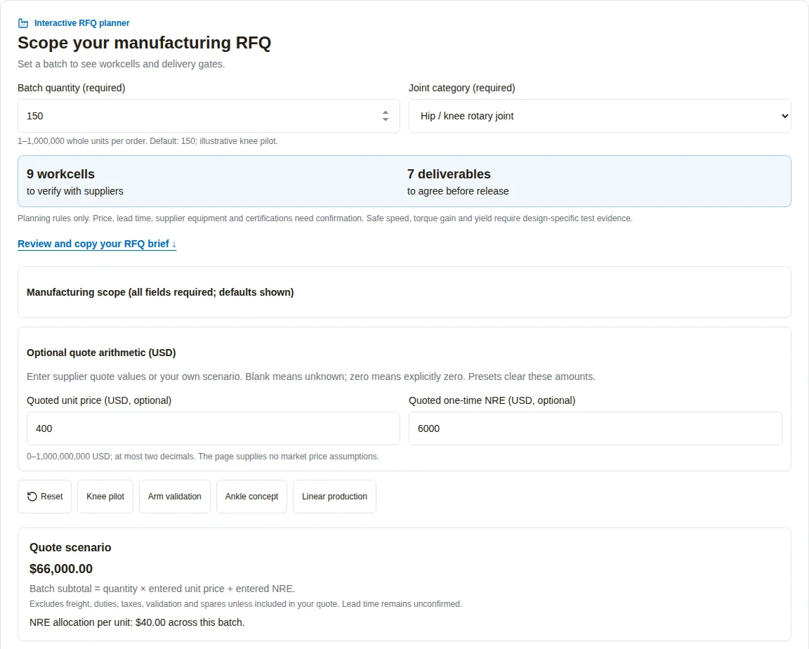
Select Knee pilot, keep its default PVT, co-engineering, safety review, conductive potting, CFRP sleeve and component screening proposals, then enter 150 units, USD 400 per unit and USD 6,000 NRE. The result is nine workcells to verify, seven deliverables to agree and a USD 66,000 batch subtotal. These are synthetic inputs.
Illustrative planning scenarios
Hypothetical examples and reproducible arithmetic; no customer results or measured supplier performance are claimed.
Illustrative scenario: knee joint pilot
Premise: A team proposes 150 knee units at PVT with potting and sleeve retention. These are example inputs, not a customer record.
Process: The planner adds load-fixture, potting and screening review items. Ask for pilot yield, duty-cycle thermal data and rotor validation.
Decision / result: Decision gate: proceed only after design release and pilot evidence acceptance. Yield, safe speed and torque gain remain unknown.
Illustrative scenario: arm joint validation
Premise: A released arm design needs 35 DVT samples under a build-to-print agreement.
Process: Assign customer drawing authority, insulation checks, calibration records and application endurance qualification.
Decision / result: Decision gate: compare validation scope and deviation handling before ordering. No cost saving or performance outcome is claimed.
Illustrative scenario: sealed ankle concept
Premise: An ankle differential needs 10 concept samples with a proposed sealed enclosure.
Process: The planner adds coupled-axis checks. Request environmental qualification and establish whether a production leak screen can be correlated.
Decision / result: Decision gate: resolve linkage interference and seal design before pilot tooling. The selected review focus does not grant an IP rating.
Worked arithmetic example: linear joint batch
Premise: Synthetic amounts only: one batch of 150 units, an entered unit price of USD 400 and entered NRE of USD 6,000.
Process: 150 × 400 + 6,000 = USD 66,000. NRE allocation is 6,000 ÷ 150 = USD 40 per unit.
Decision / result: The arithmetic helps normalize quotes; it is not a supplier price. For a linear joint the scope also needs screw alignment, thrust / stroke and axial play inspection.
Engineering and sourcing questions
RFQ preparation
What is the minimum information for a useful RFQ?
Send drawing / BOM revisions, application load and duty cycle, interfaces, batch quantity, annual forecast, target dates and delivery location. Mark unresolved items explicitly so feasibility work can be quoted separately.
Can I start without released CAD?
Yes, request a feasibility or co-engineering scope. Identify who will create and approve missing drawings; separate that engineering work from a recurring production quotation.
Do the presets describe real customer projects?
No. They are illustrative scope examples. They contain no verified customer outcomes, price commitments or equipment availability claims.
Tool method
How does the planner choose workcells?
It starts with six process review areas and adds items for joint architecture, potting and component cleanliness / screening. Stage and ownership selections add delivery gates. All rules run locally and are deterministic.
How are budgets calculated?
Only from your own entered quote or scenario values: batch subtotal equals quantity times unit price plus one-time NRE. Blank values remain unknown; explicit zero is accepted. There is no inferred market price or volume discount.
Does this tool predict safe rotor speed, thermal gains or yield?
No. Those require design dimensions, material and cooling data, an agreed test method and measured results. A selected sleeve, resin or production stage is insufficient.
What if the quote is unknown or the batch is outside the tool range?
Keep optional quote fields blank. The batch range is 1 to 1,000,000 whole units for this planner, not a supplier MOQ. For other quantities request a manual scope review using the inquiry section.
What if copying fails or JavaScript is unavailable?
If clipboard access fails, the brief is selected for manual copying. With JavaScript disabled use the report checklist and inquiry section for a manual RFQ review.
Validation
Does ISO 16232 require a 25 µm particle limit?
No. Its component cleanliness inspection framework does not supply application-specific limits. The customer and supplier must agree controlled surfaces, reporting and acceptance limits. See the linked ISO source.
Does an ISO cleanroom class prove gearbox cleanliness?
No. Room air classification and component particulate inspection answer different questions. Request evidence for both controls when the application requires them.
Is a standard thermal shock cycle mandatory for every inverter?
No. Environmental conditions and the screening or qualification profile need an approved, application-specific test plan. MIL-STD-810 describes tailoring; it does not supply one universal powered screen.
Is IPC Class 3 or a space addendum always required?
No blanket requirement is made here. Agree the IPC revision, acceptance class, inspection scope and any addendum with the electronics owner in the purchase specification.
What is the difference between DVT and production EOL testing?
DVT validates the design against intended loads and environment. EOL releases manufactured units against agreed checks. A short production screen needs evidence of correlation before replacing a longer validation measurement.
Does a safety review selection certify the actuator?
No. The integrator must define the safety functions and evidence needed from components, then validate the assembled system. The planner only adds review questions.
Commercial decisions
What are the MOQ and delivery lead time?
They are unconfirmed here. Request a dated quotation that states batch size, design maturity, material availability, tooling readiness, capacity assumptions and delivery terms.
Must all manufacturing happen in one factory?
Specify the control and traceability required. A supplier may use approved specialists if ownership, inspection handoffs, changes and final release remain explicit. Verify the actual route before award.
How should customer-funded tooling be handled?
List each asset, the agreed ownership, permitted use, calibration and maintenance responsibility, storage, inspection access and retrieval terms in the manufacturing agreement. Funding alone does not document those terms.
What is the next step after building the brief?
Copy the brief, attach your engineering package and send it through the inquiry section. Ask the supplier to confirm open items, proposed workcell routing, acceptance evidence, itemized NRE and quote validity.
Sources, scope and evidence limits
Public publisher summaries checked on October 26, 2026. Consult the full adopted revision and contract requirements for implementation; these references do not certify any supplier or actuator.
Editorial review owner: Magatom Dynamics Co., Ltd.. Next review by April 26, 2027, or sooner after a source revision, tool rule change or substantiated buyer correction.
- ISO 16232:2018 — component cleanliness
Particle inspection and reporting methods for road-vehicle components; a possible contractual method for actuator parts.
Boundary: No component-specific cleanliness limits are supplied. Robotics applicability and limits need agreement.
- ISO 14644-1:2015 — air cleanliness classification
Classifies airborne particle concentration in cleanrooms and clean zones.
Boundary: A room class does not establish the cleanliness of an assembled gearbox or certify an actuator.
- DLA ASSIST — MIL-STD-810H, Change 1
Environmental test planning and tailoring to the equipment life cycle.
Boundary: No universal powered screening profile or certification is implied. Use an approved test plan.
- IPC — IPC-A-610J and J-STD-001J release
Distinguishes assembly acceptance from soldering process and material requirements.
Boundary: Agree the revision, class and inspection plan in the purchase specification; a space addendum is not automatically applicable.
- ISO 13849-1:2023 — safety-related control design
A design methodology for safety-related parts of control systems.
Boundary: The application safety functions and required performance levels are not selected by this RFQ tool.
Request a Contract Manufacturing DFM & Quote Review
Send your 3D STEP assembly, 2D GD&T drawings, and target volume requirements. Our manufacturing engineering team will evaluate workcell routing, tooling NRE, and provide formal ex-works quotations.
Inquiry Email
Include target torque/speed, quantity, and delivery location.
Application Engineer
WhatsApp Engineering Support
Talk directly about drawings, torque-speed targets, and RFQ data gaps.